06-28-2012, 10:19 PM
(This post was last modified: 06-28-2012, 11:03 PM by henryarnold.)
I just bought a Meister DRO for my Grizzly 10x22 Lathe. Meister DROs are similar to Sino which are made in Asia. Meister is based in Singapore and has a storefront on EBay which is where I bought my setup. Three years ago I bought a Meister 3 axis DRO for my milling machine. Its been a great unit so I decided to go with Meister again.
The base price of the unit I'm going to show photos of was $468 including shipping from Singapore. There are cheaper setups but not much cheaper for a setup with glass scales. I also paid extra to get the smaller cross slide scale.
I have no affiliation with Meister but if you want to check them out, here's where I bought my setup:
http://www.ebay.com/itm/Meister-ARC2-dig...1e604706ed
When you comparison shop, be sure to note the shipping cost. There are a few EBay vendors with similar setups for $320 but their shipping is $125!!
I'll be documenting my installation with photos and text. There are many ways to install a DRO and there are a variety of DRO types so this is just one example. I found that looking at how someone else tackled installation issues was helpful to me so I hope this post will be helpful to the group.
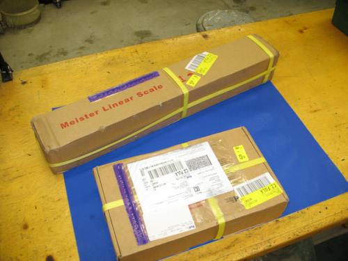
The shipping took only 6 days which is very fast. Sometimes it can take longer. The shipment came in 2 boxes. Meister ships your display in one box and the custom scales you select in a second box. They are very helpful in making sure you pick the correct scale size.

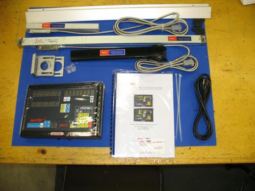
Here's everything unpacked. Everything made it without damage. The kit includes the display which has all kinds of layout calculations and aids, mounting brackets, hardware, and a manual.

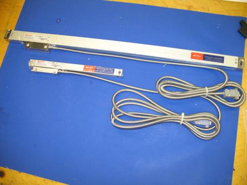
I selected a 570 mm scale for my carriage and a 170 mm scale for my cross slide. These are well made units. They have double rubber lips to keep oil and debris out of the scale. There are no plastic parts and the cable is armoured for protection.

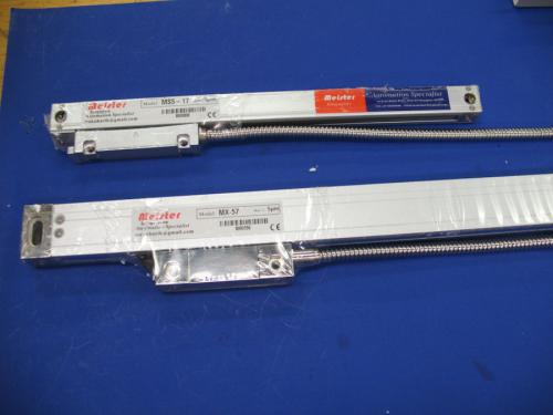
In this closeup you can see that my cross slide scale is much smaller than the carriage scale. For larger lathes, it is not necessary to order the small scale. The normal size scale will usually fit on most lathes. My lathe is small so I decided it would be easier with the small scale.

The base price of the unit I'm going to show photos of was $468 including shipping from Singapore. There are cheaper setups but not much cheaper for a setup with glass scales. I also paid extra to get the smaller cross slide scale.
I have no affiliation with Meister but if you want to check them out, here's where I bought my setup:
http://www.ebay.com/itm/Meister-ARC2-dig...1e604706ed
When you comparison shop, be sure to note the shipping cost. There are a few EBay vendors with similar setups for $320 but their shipping is $125!!
I'll be documenting my installation with photos and text. There are many ways to install a DRO and there are a variety of DRO types so this is just one example. I found that looking at how someone else tackled installation issues was helpful to me so I hope this post will be helpful to the group.
The shipping took only 6 days which is very fast. Sometimes it can take longer. The shipment came in 2 boxes. Meister ships your display in one box and the custom scales you select in a second box. They are very helpful in making sure you pick the correct scale size.
Here's everything unpacked. Everything made it without damage. The kit includes the display which has all kinds of layout calculations and aids, mounting brackets, hardware, and a manual.
I selected a 570 mm scale for my carriage and a 170 mm scale for my cross slide. These are well made units. They have double rubber lips to keep oil and debris out of the scale. There are no plastic parts and the cable is armoured for protection.
In this closeup you can see that my cross slide scale is much smaller than the carriage scale. For larger lathes, it is not necessary to order the small scale. The normal size scale will usually fit on most lathes. My lathe is small so I decided it would be easier with the small scale.
henryarnold, proud to be a member of MetalworkingFun Forum since Apr 2012.


![[Image: TomsTechLogo-Profile.png]](http://tomstechniques.com/wp-content/uploads/2013/11/TomsTechLogo-Profile.png)


![[Image: X-scale_top_right.jpg]](http://img.photobucket.com/albums/v466/kenm10759/Dads%20shop/X-scale_top_right.jpg)
![[Image: X_scale_low_right.jpg]](http://img.photobucket.com/albums/v466/kenm10759/Dads%20shop/X_scale_low_right.jpg)
![[Image: X_slide_rear.jpg]](http://img.photobucket.com/albums/v466/kenm10759/Dads%20shop/X_slide_rear.jpg)
![[Image: IMG_0220-r.jpg]](http://img.photobucket.com/albums/v466/kenm10759/Dads%20shop/IMG_0220-r.jpg)
![[Image: IMG_0221-r.jpg]](http://img.photobucket.com/albums/v466/kenm10759/Dads%20shop/IMG_0221-r.jpg)
![[Image: Z_slide_low_right.jpg]](http://img.photobucket.com/albums/v466/kenm10759/Dads%20shop/Z_slide_low_right.jpg)
![[Image: Z_scale_low_rear.jpg]](http://img.photobucket.com/albums/v466/kenm10759/Dads%20shop/Z_scale_low_rear.jpg)