Posts: 14
Threads: 2
Joined: Nov 2014
Location: N. Lincolnshire, UK
02-27-2016, 08:31 AM
(This post was last modified: 02-27-2016, 08:33 AM by rotorhead.
Edit Reason: syntax error
)
Hi Folks,
After 20 odd years of manual ownership of my Colchester Master, I finally had a DRO fitted...
I liked the anticipated accuracy I thought I would get, but found that the cross slide moved even with the dial locked.
In the past I have added a lock screw to both the cross slide, and top slide, hoping that would eliminate any feedscrew movement.
However even with the cross feedscrew locked, I have 0.002" movement of the toolpost/topslide, indicated by the DRO.
On my machine there is a taper turning attachment, so I thought it was accumulated movement of the guides, there are three, the main base slideway, the top taper slideway and the trunnion in that top slide, with the cross slide feedscrew bearing.
Having tightened all these to minimal movement, and taken up any backlash from the cross slide feedscrew nut, I still have 0.002" travel indicated by the DRO.
I'm now proposing to concoct a cross slide clamp arrangement.
Easier said than done as there are several points to consider.
The only suitable place on the apron is in front of the cross slide in a 'T' slot used by the travelling steady.
That puts it near to rotating parts (Chuck and work in chuck).
My idea is leaning towards an 'L' shaped arm connected to a clamping teenut.
With a LH thread to allow it to come round to the operator side of the cross slide, keeping it clear of the chuck and any carriage stop arrangement.
This is something I'll have to get on with so will post some pics of the progress. 
Chris Wright
North Lincolnshire.UK
Colchester Master 6 1/2"(13"), Elliott Rapidmil, Clarkson MkI+
Posts: 8,739
Threads: 313
Joined: Feb 2012
Location: Arizona/Minnesota
Sounds like you might need a new cross slide lead screw and/or nut. 
Ed
Posts: 716
Threads: 32
Joined: Apr 2012
Location: Washington, USA
I was thinking a cracked gib or something. Disassemble, clean and inspect.
On the other hand, what is the reason for locking the cross slide?
Posts: 8,739
Threads: 313
Joined: Feb 2012
Location: Arizona/Minnesota
(02-27-2016, 10:04 AM)Sunset Machine Wrote: what is the reason for locking the cross slide?
I lock it when I'm doing a finishing cut using the power feed and want an accurate diameter the entire length of the cut.
Ed
Posts: 79
Threads: 12
Joined: Dec 2013
Location: mansfield UK
Have you double checked the dro tightening fitting or as above a broken gibe slide
mfletch, Try to do the best you can and that's good enough
Posts: 716
Threads: 32
Joined: Apr 2012
Location: Washington, USA
(02-27-2016, 10:49 AM)EdK Wrote: (02-27-2016, 10:04 AM)Sunset Machine Wrote: what is the reason for locking the cross slide?
I lock it when I'm doing a finishing cut using the power feed and want an accurate diameter the entire length of the cut.
Ed
I can see it necessary with the work mounted on the saddle, but not for general turning. Sounds like dirt or a broken thing someplace causing a poor fit and clamping shifts it around. I'd disassemble and clean it someday but quit clamping now.
Posts: 14
Threads: 2
Joined: Nov 2014
Location: N. Lincolnshire, UK
Hi again Folks,
Saddle and cross-slide were disassembled not long ago, there is no side movement only 'X' movement against the feedscrew/nut/trunnion bearing assy.
The comment about wear in my crossfeed screw is valid, as I can takeup backlash via the adjustable nut, whilst I can get zero backlash at one point this is not true of all the travel, so maybe a new feedscrew and nut would be a last resort.
I would have to make these, as new replacement would probably cost more than the value of the lathe.
Should this become necessary, then a home brew single start would be the result, I've already done this exercise on my son's Bantam 800, with excellent accuracy results.
I'll post some pics tmoro of where the trouble lies.
Thanks for commenting Folks.
Chris Wright
North Lincolnshire.UK
Colchester Master 6 1/2"(13"), Elliott Rapidmil, Clarkson MkI+
Posts: 8,739
Threads: 313
Joined: Feb 2012
Location: Arizona/Minnesota
(02-27-2016, 12:21 PM)Sunset Machine Wrote: , but not for general turning.
Why? 
Ed
Posts: 14
Threads: 2
Joined: Nov 2014
Location: N. Lincolnshire, UK
Hi,
Took some pics.
Trouble is, when one thinks about it, if the cross-slide isn't locked, it can effectively 'float' against the feedscrew and any accumulated slackness in said arrangement.
The tool will be deflected by whatever cutting forces, and follow its own path dependent upon those forces.
If the tool via the cross-slide is locked, it has to remain in a fixed positional axis, and hopefully turn a true cylinder...
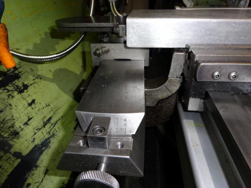
Complete picture of front of the Cross-Slide, showing the Dial lock etc...

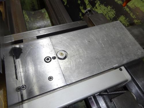
The Taper Attachment showing the three points of suspected accumulated movement...
The Cross-Slide Antibacklash Adjustment Screws...
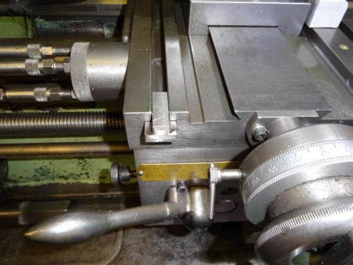
The proposed TEE nut to slide along the Travelling Steady TEE slot...
Chris Wright
North Lincolnshire.UK
Colchester Master 6 1/2"(13"), Elliott Rapidmil, Clarkson MkI+
Posts: 642
Threads: 14
Joined: Oct 2013
Location: East Sussex, UK
The following 1 user Likes awemawson's post:
EdK (02-28-2016)
02-28-2016, 08:34 AM
(This post was last modified: 02-28-2016, 08:39 AM by awemawson.)
Chris,
I filed this away years ago:
Home Machinist
Telescoping Taper Attachment Modification (Long)
Posted By: Dave Milosevich [San Pedro, PRC] <mailto:canddmil@pacbell.net?subject=Telescoping Taper Attachment Modification (Long)>
Date: Wednesday, 11 September 2002, at 9:29 p.m.
When I acquired the 15" Clausing-Colchester in the link below, I was looking forward to having a taper attachment available for use on demand. Though built in the mid 1980's, the machine had seen essentially no use when I purchased it in early 2001. So it was surprising when I had difficulty in simple turning tasks of hitting a specific diameter on the workpiece. Hooking a dial indicator to the cross slide revealed that the tool infeed travel varied as much as .004" with respect to the dial on the crossfeed handwheel. This just did not make sense. Backing the tool out by two or three complete revolutions before going back in an equal distance, plus depth of cut, would mitigate the problem somewhat. If the tool was not backed out at all at the end of a pass and only fed in the desired depth before beginning the next cut, the problem was also less evident. So there were ways to work around the problem when just turning. But when threading, the problem was a PITA.
What I discovered was that the telescoping taper attachment's components had clearances that were stacking up. All the play was not consistently removed when the crossfeed handwheel was turned in opposite directions in small (less than 2 or 3 complete revolutions) increments. Don't misunderstand - backlash was not two or three complete revolutions. The amount of handwheel rotation required to actually reverse the direction of cross slide travel was about .010". The problem was that it might be .010" one time and .008" or .012" the next. And backing out, say, .100" and returning to the desired setting did not make it more consistent.
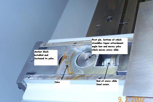
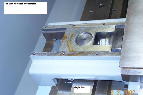
Backlash is usually just the sum of the crossfeed screw/nut assembly and the screw/thrust bearing clearances. The addition of the taper attachment included the pivot/yoke, angle bar/straddle, and dovetail/casting assembly clearances in the mix. All manner of fiddling with gib, thrust bearing, and cross slide nut adjustments did little good. This may have worked itself out as wear allowed all of the components to settle more easily against one another when the various tensions and pressures were inverted upon cross slide reversals. But I've got stuff to do now and did not want to deal with it any longer.
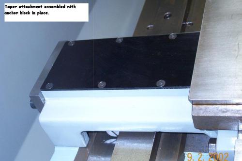
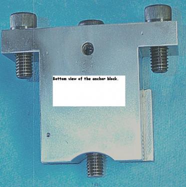
The solution arrived at was to anchor the yoke to the taper attachment casting which is bolted to the carriage saddle. This eliminated all of the clearances between the moving taper attachment parts. To use the taper feature, the three cap screws and block are removed and the attachment works normally. The fix works great. Only a few thousandths rotation of the cross slide feed wheel beyond removing the backlash, enables repetition of the tool feed distance within a very few tenths. Backlash itself was reduced to less than .004".
Clicking on the link should take you to my first, modest attempt at standing up a web page with images. The various links there should show some photos of what I was trying to describe above.
Andrew Mawson, proud to be a member of MetalworkingFun Forum since Oct 2013.
|


