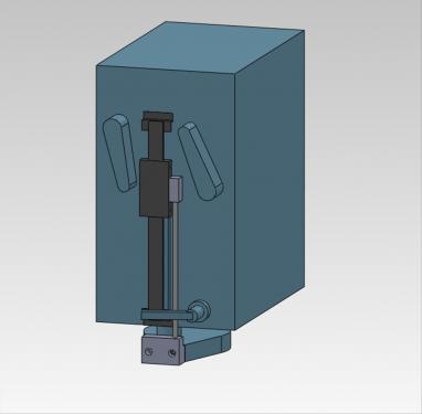
This is my first project on my Enco 45 clone mill. I purchased an expensive DRO for the z-axis quill and researched similar installations on the web. I modeled the mill head, quill and gear levers so I could layout the DRO and design mounts. Here is a screen shot of the assembly.
The next shots are of the upper mount installed on the back of the DRO.
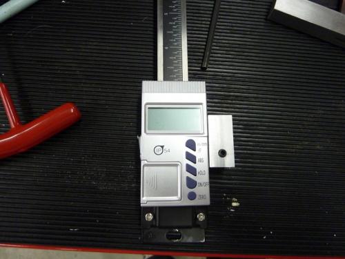
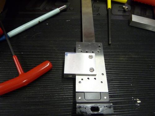
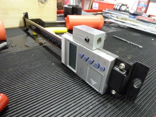
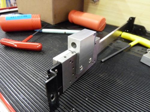
I didn't get any pictures of just the mount but it is milled from a single piece of scrap I got from work. There are 2 countersunk holes for the supplied 3mm screws to mount to the DRO and a .25" hole and 10-24 set screw for the tie bar.
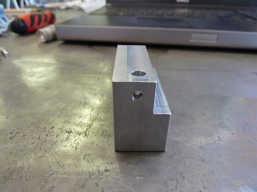
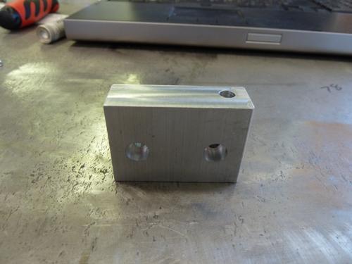
Here's the lower mount milled to size.
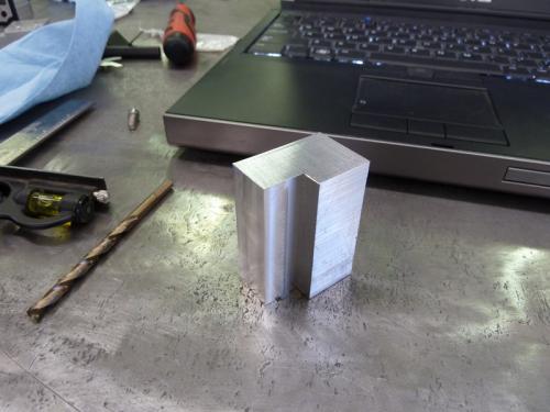
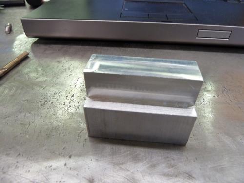
I next added 2 countersunk mounting holes for 10-24 SHCS and another .25" hole and set screw for the tie bar.
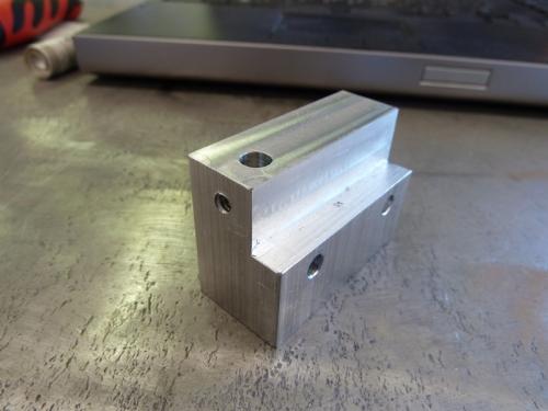
The DRO was mounted to the mill head with 2 10-24 screws. I drilled these free hand into the casting and tapped them by hand being very careful to not break off the tap.
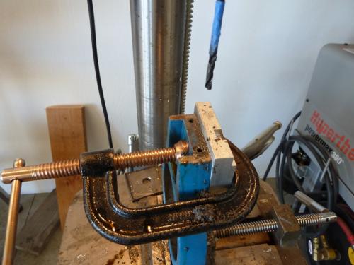
The lower mount to bolted to the depth gage mount plate that clamps to the quill. I did this on the drill press. Here is the setup on the drill press.
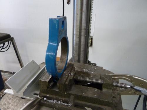
and the finished holes
This final shots are of the finished installation.
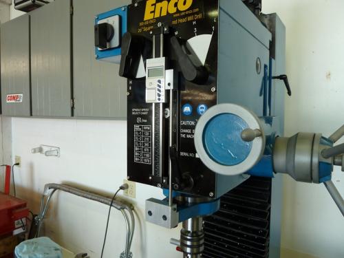
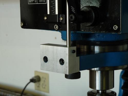
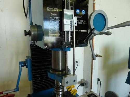
It works great and was a fun project to learn on.
The next shots are of the upper mount installed on the back of the DRO.
I didn't get any pictures of just the mount but it is milled from a single piece of scrap I got from work. There are 2 countersunk holes for the supplied 3mm screws to mount to the DRO and a .25" hole and 10-24 set screw for the tie bar.
Here's the lower mount milled to size.
I next added 2 countersunk mounting holes for 10-24 SHCS and another .25" hole and set screw for the tie bar.
The DRO was mounted to the mill head with 2 10-24 screws. I drilled these free hand into the casting and tapped them by hand being very careful to not break off the tap.
The lower mount to bolted to the depth gage mount plate that clamps to the quill. I did this on the drill press. Here is the setup on the drill press.
and the finished holes
This final shots are of the finished installation.
It works great and was a fun project to learn on.
Collecting tools for 30 years.


