08-19-2017, 04:27 PM
One of my lathes is a small Austrian-made Emco-Maier 8 x 18. It’s a remarkably rigid machine, short and stout, capable of work that many medium size lathes cannot duplicate. But it has limitations, small work envelope, no QC gear box and non-optimum toolpost..
This lathe had been lightly used when I bought it nearly thirty years ago and it was equipped with a four-way tool post. I’m going to start this thread by noting that I have much fondness for both the four-way tool post and the Armstrong tool system, also known as the American tool system.
I have an inexpensive Aloris-Dorian-style QCTP mounted on the larger lathe and it mostly works just fine but the Armstrong system – properly deployed – in my opinion can be the best combination of versatility and rigidity for one-off work. Further comments expanding this opinion will follow below.
But let’s first get back to the four-way tool holder on the small lathe. Since I purchased the machine in 1980, rarely was the four-way tool holder removed except to mount a shop-made boring bar.
For demonstration purposes, here’s a comparison of the boring holder compared to the QCTP boring bar holder, note the difference in tool overhang..
Boring bar is ¾ diameter steel holding a 1/2 shank C2/C6 carbide boring tool or ¼ HSS cutting tool in 1/2 adapter
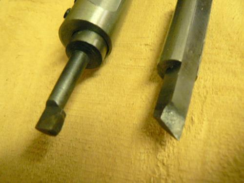
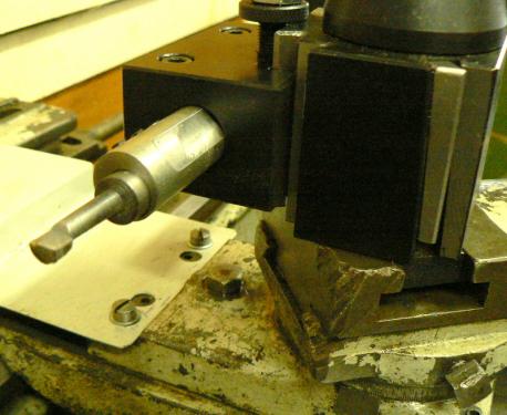
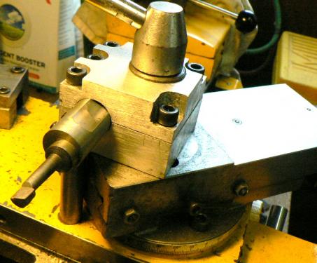
Let’s acknowledge that boring usually entails a fairly shallow DOC so rigidity may be of lesser concern but the above is a useful illustration of how the QCTP may fall short in rigidity - and the example applies to any tool installed in the QCTP holder to a greater or lesser degree.
The Armstrong system, if it is used casually and without much thought, will be even worse.
Some ten or twelve years ago, I decided to make a few simple tool holders with much better performance than the original four way tool holder.
I made the tool holders shown below which work quite well. The height of the tool holders and the slot depths were cut to the correct depth so that the tips of cutting tools were on center when the tool holder was mounted to the compound slide. There is no tool post, each tool holder is mounted directly to the compound slide.
I made holders for three commonly used cutting tools, 3/8 square HSS tool, a knurling holder and a 3/32 holder for a parting blade. (BTW, the tool overhangs are NOT typical, just posed for the photo !)
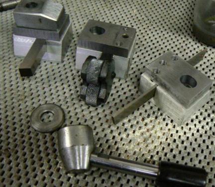
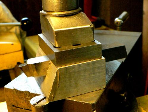
These are about as sturdy as a tool holder can be for a small lathe. They mount at a near-optimum location using the same mounting stud as the four way tool holder. Although I don’t use these holders routinely, they are handy for special needs, notably heavy cutting, including single-pointing large threads.
But why not just use the Aloris-style, like everyone else ?
Small lathes must employ every trick one can devise to improve rigidity. QCTP designs are highly convenient and fairly repeatable (the “real” ones are VERY precise) but they are, arguably, the second worst tool post in common hobbyist use for rigidity.
This is mainly due to the distance from the mounting stud to the actual cutting edge of the tool. It’s quite a long way, relatively speaking, and the tool is pretty much just hangin’ in mid-air. That distance creates a cantilevered load that tends to lift and tilt both the compound slide AND the cross slide, a condition that can lead to chatter.
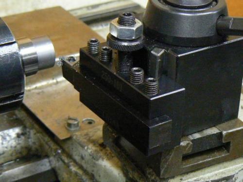
Any tool holder will exhibit similar behavior but most, due to the shorter distance from tool tip to mounting location, have less leverage and hence less cross slide loading. A method that keeps the cutting tool as near the center of the cross slide as possible will generally be the best one.
There are special cases and conditions, of course. A configuration used for heavy industrial turning at Westinghouse Marine Division while I was employed there, was to mount the cutting tool upside down and run the lathe in reverse.
This will also cause the cross slide to lift (compound slides were rarely mounted) but the force tends to push the cross slide dovetails more tightly together rather than apart, which is far better for preventing chatter.
A variation is the rear-mounted tool post (on the opposite side of the carriage from the normal tool post) with upside down tool which accomplishes the same effect to a degree. This configuration allows the lathe to be operated in the forward direction. (An obvious advantage is that the two tool posts – one on each side of the carriage - can be used simultaneously to perform different operations.)
Returning to the topic of the four way tool post, parting operations were sometimes uncomfortable on the Emco-Maier. Depicted below is the original, still in use, four-way tool holder. It is normally loaded with a cut-off blade, a sharp HSS right hand turning tool and a carbide insert tool holder.
One station is left vacant for special needs like a small boring tool. All cutting tools are held in shop-made holders fabricated so that the installed cutter is positioned at the correct height. Tools may be removed, sharpened and replaced without re-positioning provided that the cutting edge height is not reduced. (This has not been a problem so far.)
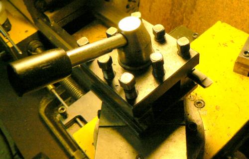
The further left corner (closest to headstock) of the toolpost bears the load from the cutting process. Like QCTP tool holders, that corner was unsupported and just hangin’ out in space. By tightening the front grub screw, one of the two that clamp the cutting tool, it was observed that the corner deflected under modest pressure.
Although this wouldn’t seem to be a major problem, it occurred to me that if the cutting force of the parting tool could be directed straight down at the cross slide rather than behaving as a lever and minimizing the tool post deflection, the lathe would be WAY happier. A further advantage is that any flexibility in the compound slide is no longer a problem.
A fifteen minute chore justified this premise. I made a steel post to support the “weak” corner of the four-way tool holder – the point of maximum cutting load. The post is threaded into a tapped hole on the cross-slide. (I should note that I keep my compound slides more or less permanently angled at 30 degrees, which determined the location of the post.)
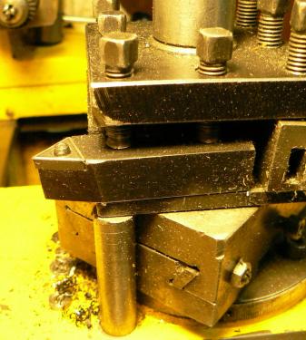
Compound slide retracted and tool post rotated a bit for a different view:
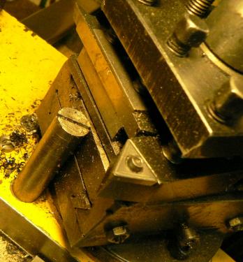
And with the support unscrewed when the compound rest needs to be advanced or rotated::
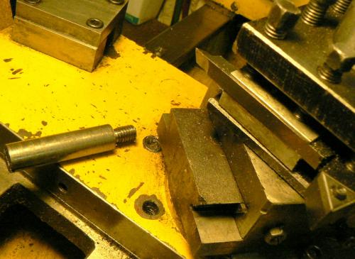
(continued in Part 2)
This lathe had been lightly used when I bought it nearly thirty years ago and it was equipped with a four-way tool post. I’m going to start this thread by noting that I have much fondness for both the four-way tool post and the Armstrong tool system, also known as the American tool system.
I have an inexpensive Aloris-Dorian-style QCTP mounted on the larger lathe and it mostly works just fine but the Armstrong system – properly deployed – in my opinion can be the best combination of versatility and rigidity for one-off work. Further comments expanding this opinion will follow below.
But let’s first get back to the four-way tool holder on the small lathe. Since I purchased the machine in 1980, rarely was the four-way tool holder removed except to mount a shop-made boring bar.
For demonstration purposes, here’s a comparison of the boring holder compared to the QCTP boring bar holder, note the difference in tool overhang..
Boring bar is ¾ diameter steel holding a 1/2 shank C2/C6 carbide boring tool or ¼ HSS cutting tool in 1/2 adapter
Let’s acknowledge that boring usually entails a fairly shallow DOC so rigidity may be of lesser concern but the above is a useful illustration of how the QCTP may fall short in rigidity - and the example applies to any tool installed in the QCTP holder to a greater or lesser degree.
The Armstrong system, if it is used casually and without much thought, will be even worse.
Some ten or twelve years ago, I decided to make a few simple tool holders with much better performance than the original four way tool holder.
I made the tool holders shown below which work quite well. The height of the tool holders and the slot depths were cut to the correct depth so that the tips of cutting tools were on center when the tool holder was mounted to the compound slide. There is no tool post, each tool holder is mounted directly to the compound slide.
I made holders for three commonly used cutting tools, 3/8 square HSS tool, a knurling holder and a 3/32 holder for a parting blade. (BTW, the tool overhangs are NOT typical, just posed for the photo !)
These are about as sturdy as a tool holder can be for a small lathe. They mount at a near-optimum location using the same mounting stud as the four way tool holder. Although I don’t use these holders routinely, they are handy for special needs, notably heavy cutting, including single-pointing large threads.
But why not just use the Aloris-style, like everyone else ?
Small lathes must employ every trick one can devise to improve rigidity. QCTP designs are highly convenient and fairly repeatable (the “real” ones are VERY precise) but they are, arguably, the second worst tool post in common hobbyist use for rigidity.
This is mainly due to the distance from the mounting stud to the actual cutting edge of the tool. It’s quite a long way, relatively speaking, and the tool is pretty much just hangin’ in mid-air. That distance creates a cantilevered load that tends to lift and tilt both the compound slide AND the cross slide, a condition that can lead to chatter.
Any tool holder will exhibit similar behavior but most, due to the shorter distance from tool tip to mounting location, have less leverage and hence less cross slide loading. A method that keeps the cutting tool as near the center of the cross slide as possible will generally be the best one.
There are special cases and conditions, of course. A configuration used for heavy industrial turning at Westinghouse Marine Division while I was employed there, was to mount the cutting tool upside down and run the lathe in reverse.
This will also cause the cross slide to lift (compound slides were rarely mounted) but the force tends to push the cross slide dovetails more tightly together rather than apart, which is far better for preventing chatter.
A variation is the rear-mounted tool post (on the opposite side of the carriage from the normal tool post) with upside down tool which accomplishes the same effect to a degree. This configuration allows the lathe to be operated in the forward direction. (An obvious advantage is that the two tool posts – one on each side of the carriage - can be used simultaneously to perform different operations.)
Returning to the topic of the four way tool post, parting operations were sometimes uncomfortable on the Emco-Maier. Depicted below is the original, still in use, four-way tool holder. It is normally loaded with a cut-off blade, a sharp HSS right hand turning tool and a carbide insert tool holder.
One station is left vacant for special needs like a small boring tool. All cutting tools are held in shop-made holders fabricated so that the installed cutter is positioned at the correct height. Tools may be removed, sharpened and replaced without re-positioning provided that the cutting edge height is not reduced. (This has not been a problem so far.)
The further left corner (closest to headstock) of the toolpost bears the load from the cutting process. Like QCTP tool holders, that corner was unsupported and just hangin’ out in space. By tightening the front grub screw, one of the two that clamp the cutting tool, it was observed that the corner deflected under modest pressure.
Although this wouldn’t seem to be a major problem, it occurred to me that if the cutting force of the parting tool could be directed straight down at the cross slide rather than behaving as a lever and minimizing the tool post deflection, the lathe would be WAY happier. A further advantage is that any flexibility in the compound slide is no longer a problem.
A fifteen minute chore justified this premise. I made a steel post to support the “weak” corner of the four-way tool holder – the point of maximum cutting load. The post is threaded into a tapped hole on the cross-slide. (I should note that I keep my compound slides more or less permanently angled at 30 degrees, which determined the location of the post.)
Compound slide retracted and tool post rotated a bit for a different view:
And with the support unscrewed when the compound rest needs to be advanced or rotated::
(continued in Part 2)


