Posts: 968
Threads: 67
Joined: Apr 2015
Location: Australia
 01-05-2018, 03:00 AM
(01-04-2018, 08:32 AM)f350ca Wrote: Its an interesting idea, just because its not done YET doesn't mean it wouldn't work. Could you make a core of sand or carbon or what ever that would break out after.
Pouring the bushes with a sand core would be a good way of getting bronze into the holes, but it would still leave the problem of needing to line-bore the resulting cast bores in order to get the pins on the same plane across the two arms. Probably easier just to press bushes into the bored arms and then line-bore the bushes.
(01-04-2018, 09:27 PM)randyc Wrote: (01-04-2018, 03:50 AM)Pete O Wrote: ......I've come up with an idea to use the head off my drill press to turn and feed a shaft with a boring tool on the other end, might just be crazy enough to work...
I LOVE crazy ideas, even if they have 50% chance of working ! As a guy on YouTube, whose name I have now forgotten, said "Every day is a school day in the machine shop".
Will you use an outboard bearing for the drill press ? Hope that you photograph and post the setup, Pete, even if it doesn't perform as well as you'd like. Even partial successes (NOT implying that your idea will be anything but successful) are very useful as a learning tool !!!
Cheers !
Here's a verbal sketch of what I have in mind: A length of I-beam welded across the two loader arms, parallel to where the bores will be; Pillow-block bearings mounted to the I-beam, between the loader arms, so that the bearing I.D. is on the bore axis; A length of shaft that goes through the bearings, one end carries the HSS tool bit, the other end protrudes through the other (rough finished) hole and has 3 flats machined on it to be driven by a drill chuck; the drill-press head mounted outboard of the frame so that the drill press spindle is on the bore axis and that end of the boring shaft is driven by the drill press chuck, feed being via the quill. The shaft has holes drilled across it at appropriate points to position a HSS toolbit for each bore location, the toolbit being adjusted manually between cuts. In an ideal world, a J-head takes the place of the drill-press head and I stand back and smile while the power feed does all the work  . .
(01-05-2018, 01:20 AM)SteveG Wrote: In a previous life, we used to replace the hard bronze bushings that attach the engines to the wing pylons on B747's.
The bushes were fitted using liquid nitrogen to shrink them then the machinists would line bore them in place.
My memory is a bit sketchy as its been 20+ years, but I don't recall the tooling being complex, and was just driven using large right angle pneumatic drill (slow speed and small head for access reasons). I don't recall any mechanical feed mechanism.
Since you're not looking at a high precision application, I don't see why you couldn't get away with making up a long boring bar with a HSS cutter, and mounting 2 guide blocks - one on the outside face of each bearing and simply driving it slowly with an electric drill.
I think the feed needs to be via a quill feed or similar, a 'grab' with a drill powerful enough to drive the cutter at a 30mm radius would probably result in wrist fractures.
If you make the boring bar so its longer than the whole setup by sufficient length that you can get the cutter to the space in between the faces to adjust for the next cut, and also have a second cutter hole in the bar in the appropriate place to let you bore the other bush without disturbing the setup I think the result should be plenty good enough.
I might be able to help you out with some bronze if you don't already have some. What size are the bushes?
We're definitely on the same page Steve, although I'm picturing the bearings mounted to a length of I-beam and slightly inboard from the arms; that way I can re-use the same setup to bore the cleats on the bucket (or quick-attach frame). Nothing actually measured yet, but I think the bushes will need to be about 2" o.d. by the time I have made the existing flogged-out holes round again, and about 1 1/4" i.d. for the pins. I would look favourably upon any offers of bronze!!
Edit: re-reading you post, I think you were referring to line boring the steel pivot arms themselves. I was referring to line boring bronze bushes.
An option might be to bore the arms independently, fit bushes and then line bore them. As long as you make sure the bushes don't turn in operation the outcome should be the same.
There's a steel insert welded into the end of each arm, with badly flogged-out bores. I'll either be reboring the existing holes to accept bushes (in which case I'll line-bore the existing holes, insert bushes and then line-bore the bushes) or I will cut the inserts off and make new ones, in which case I'll pre-bore the steel inserts before welding them to the arms, then line-bore the bushes.
Steve
Lathe (n); a machine tool used in the production of milling machine components.
Milling Machine (n); a machine tool used in the production of lathe components.
Posts: 130
Threads: 17
Joined: Dec 2016
Location: Melbourne, Australia
I've definitely got a piece of cast bronze bush stock here with 53mm OD, 22 ID - about 300mm long. It might need to lose a mm or so to true up the outside diameter so might end up too small for you. No idea what spec bronze but from memory it was from the odds and sods bin at one of my local bearing suppliers.
Let me know once you've got closer measurements and I'll see what else I can find.
Steve
Posts: 968
Threads: 67
Joined: Apr 2015
Location: Australia
The following 1 user Likes Pete O's post:
f350ca (01-05-2018)
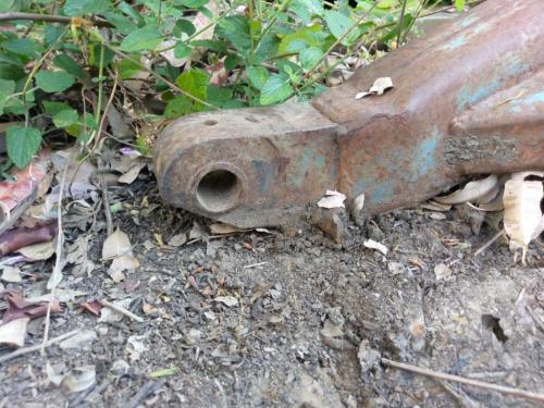
I just went out and took this photo to illustrate what I mean by the insert welded into the end of the arms. This has reminded me that the insert pieces will both need replacing, as they are worn down almost to the bores; the previous owner ran a garden supply and the geometry of the loader meant the arms dragged on the concrete every time he picked up a bucketful of sand for a customer. I have a couple of chunks of forklift tyne set aside for the replacement inserts, so I guess I'll be boring them on the mill before welding them to the loader arms, then installing the bushes and line-boring.

The repairs to the loader are probably going to have to wait a while, I'll get the tractor to a usable condition without the loader so I can do things like tow my firefighting trailer for the summer (the pressure is on for that, 41C forecast here tomorrow) and then the loader repair can go on the back-burner. I have another pressing project that will have to take precedence over the loader, my eldest daughter turns 30 in early March and her gift is yet to be designed and built.
Lathe (n); a machine tool used in the production of milling machine components.
Milling Machine (n); a machine tool used in the production of lathe components.
Posts: 2,324
Threads: 271
Joined: Jun 2014
Location: La Libertad, Philippines
This may be the time to buy or make a right angle attachment for your mill as it would lend itself better to the job than a DP. Lots of YouTube examples of ad hoc line boring to help with ideas to use existing equipment.
Posts: 968
Threads: 67
Joined: Apr 2015
Location: Australia
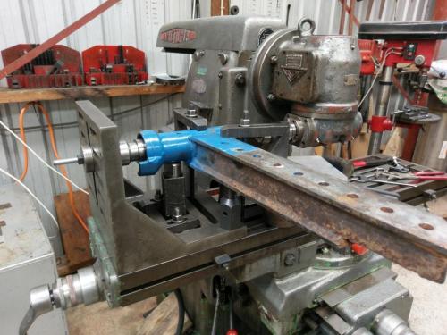
I've got one Stan! Remember the pic I posted of boring the front axle spindle a month or so ago-

but I can't see how I could bore this thing on the mill?
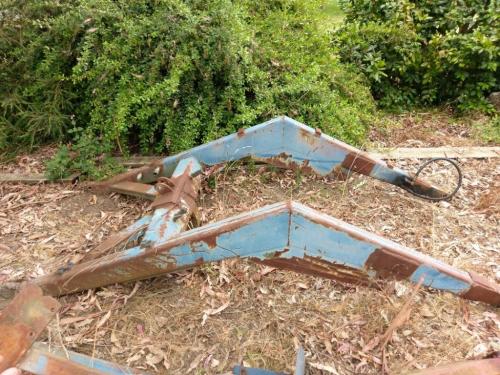
I really appreciate all the suggestions from you experienced blokes but I'm thinking that perhaps I have not explained the problem very well; I'll lay it out in detail. This is the loader frame:

It is 9 feet long and 4 feet wide and I estimate the weight at around 500lbs. The holes at the tractor end (at the right in the photo), where the frame pivots when lifted, are in excellent condition and don't need any repair.
The holes that have to be bored are at the end of the arms where the bucket is mounted, on the left in the photo. The holes have to be perfectly aligned across the frame so that as the bucket is curled, or tilted, they function as a single axis. I plan to make a quick-attach frame so that I can swap the bucket for other attachments such as a log grab, forks, etc but the fact remains that the fulcrum points must be aligned across the frame.
It may be that the above was already obvious and that I am just too thick to understand the suggestions that have been made. I just can't see how I could mount that frame on the mill; I have thought about how I could possibly do it on the lathe- the bed is long enough to fit the width of the frame- but with the weight and size of the frame I think it would be too big a risk of serious damage to the lathe- also it would involve moving a lot of things out of the way, including the milling machine.
I've looked at a lot of youtube stuff on line-boring, shop-made as well as 'proper' industrial setups. Plenty of clever solutions and good ideas.
It may be that I can get my J-head rebuild completed and use it for this job before getting it mounted on the mill, good excuse for bumping it up the project list.
Again I really appreciate all the suggestions but either I hadn't explained the problem or I'm not understanding the suggestions- probably a bit of both.
Lathe (n); a machine tool used in the production of milling machine components.
Milling Machine (n); a machine tool used in the production of lathe components.
Posts: 130
Threads: 17
Joined: Dec 2016
Location: Melbourne, Australia
The following 1 user Likes SteveG's post:
Mayhem (01-07-2018)
If you're going to be replacing the end bits completely, why not bore them, install bushes and machine to finished size before welding to the arms?
Then you've only got to deal with a jig to hold them both in alignment while you weld them in.
Steve
Posts: 4,683
Threads: 93
Joined: Feb 2012
Location: Perth, Australia
The following 1 user Likes Mayhem's post:
EdK (01-07-2018)
Steve beat me to it.
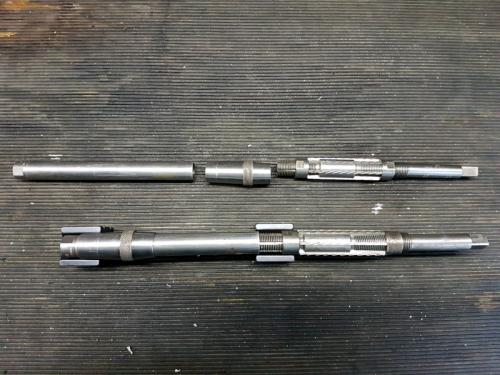
If you are worried about the post welding alignment and you have an adjustable reamer with the right capacity, you could make an extension for line reaming. Essentially, it is a piece of tube threaded to suit the reamer, with a tapered sleeve to locate the extension in the second bush, whilst you ream the first.
You could alternate sides, or you could make an additional extension and do both in one pass. That is going to get long and heavy, and you're going to have to add drive capability to the second extension.
Here is a mock up using one of my tapered reamers with an extension tube and tapered sleeve (pretend the x-blocks are bushes!):

The box of reamers I have are all inch capacity according to the label. I'm keeping an eye open for a metric set 
Hunting American dentists since 2015.
Posts: 1,827
Threads: 51
Joined: Apr 2012
Location: Oklahoma
01-08-2018, 09:37 AM
(This post was last modified: 01-08-2018, 09:38 AM by dallen.)
Like SteveG said, make new blocks install bushings. Then install the blocks on the tractor so that you can take the lift frame and put it into place and get it lined up and tack welded together and if possible finish the welding on the tractor.
this is a job that does not need a lot of precision, other then the holes in the blocks need to be bored for a press fit for the bushing. Which because of the amount of dirt and grit the will be exposed to should be hardened steel bushings similar to the ones that were originally in it. easiest thing to do on the bushings is to just buy new ones.
dallen, proud to be a member of MetalworkingFun Forum since Apr 2012.
If life seems normal, your not going fast enough! 
Posts: 3,002
Threads: 51
Joined: Apr 2012
Location: Ontario
01-08-2018, 12:47 PM
(This post was last modified: 01-08-2018, 12:48 PM by f350ca.)
I'll second dallen's idea. Hardened bushings are an off the shelf item, I used them on the backhoe. The pins wear and can easily be replaced.
Free advice is worth exactly what you payed for it.
Greg
Posts: 968
Threads: 67
Joined: Apr 2015
Location: Australia
That's something that I hadn't thought of, make the pins the wear point rather than the bushings- seems obvious when pointed out. And perhaps I've been worrying too much about the small amount of pin misalignment that will inevitably result from welding the finished items in place.
Lathe (n); a machine tool used in the production of milling machine components.
Milling Machine (n); a machine tool used in the production of lathe components.
|
 .
.


