03-08-2018, 04:34 PM
Most of the 'home brew' potter's wheels I came across on the internet had a plastic bowl of some sort around the throwing head and a lot of them were broken (like the one in the video at the start of this thread), people tend to rest their forearms on the rim while working so a plastic bowl won't last long. Commercial wheels mostly have a metal tray of some description around the head. I decided to make a steel tray and get it galvanized for long life. Had to at least get the basic design of the frame sorted so I could get the tray made and get it off to the galvanisers. Problem with designing on the go, you never quite know if something is going to work out until you get it made. I had a basic drawing of the layout and had worked out how high the thing would have to be for the pedals to clear the flywheel and the gears. I fabricated this frame out of 40x40x2mm RHS.
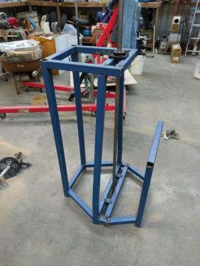
Setting it up as a mockup, I discovered that when pedalling, the side uprights were too restrictive. Decided they weren't structurally necessary so cut them off and left just the two rear uprights supporting the top frame, also shortened the top horizontal frame back to the first cross-member to mount a P-type bearing block instead of the flange mount. The flange-mount bearing in the photo above sits on the bottom frame and bears the flywheel weight axially.
I don't have any sheet-metal equipment so I had to get a local business to do the folding and rolling for the tray, got them to make a 3-sided tray 400mm wide and 100mm deep, plus roll a 100mm-wide strip to a 400mm radius, and roll an arch out of a length of 16mm round bar which would become the rim of the tray, better arm rest than a sheet-metal edge. Spent a while cutting and shutting and ended up with this

I welded four 8mm bolts to the underside so no drilling would be needed once it was galvanised. The two bits of tubing- one for a riser around the main drive shaft and the other tapered piece to put a drain hose on- were salvaged from the bicycle frame.
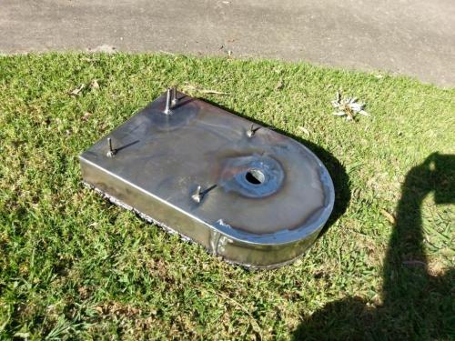
Spent a morning taking it to the galvanizing mob. I was hoping to get a look at the galvanizing process but they are a big operation with lots of things like building frames coming and going, oversize forklifts busy everywhere, I was pleased to get in and out without getting run over.
I phoned them before taking the drive to discuss where I would need holes for hanging and draining. I had made a drain hose spout in the bottom of the tray, with a little more forethought I could have positioned this where it would have worked as a zinc drain for the dipping process. I had to drill a hole in one of the bottom corners and another just under the rim opposite, need to bog these up later. Picked the finished tray up from the galvanizers last Thursday; a bit of distortion but not a problem and I don't reckon it will rust away in a hurry.
I got on with figuring out the drive mechanism in the meantime, the vertical rotation of the pedals is converted to horizontal rotation of the flywheel and throwing head by a pair of bevel gears. I've never cut gears before, I've gathered some equipment in preparation for making a couple of missing change gears for my lathe but have not got around to doing any yet. I was a bit taken aback by just how complicated bevel gears are. To make the drive mechanism with the gears and the bicycle hub work, I had to make the bevel gears a specific diameter (5 1/2") at the large end so that the bicycle hub would clear the vertical drive shaft. Unfortunately, all the calculations for bevel gears are based on the diameter of the small inner end. I spent about 3 hours making calculations and entering them into an online gear calculator until I came up with a 40-tooth 12DP 45 degree bevel gear 1 inch thick which would (a) give me the 5 1/2" large diameter and (b) use an involute gear cutter that I already had. Bevel gears don't even use a sensible gear cutter, you use a cutter for a number of teeth on some theoretical, non-existent gear based on the pitch circle of your bevel gear multiplied by some kind of voodoo spell. Anyway, I had the appropriate cutter so happy days.
I whittled away at the round lump of a casting until I had a gear blank of the appropriate dimensions. Made an arbor to mount the blanks in the lathe and in the dividing head, the two gears have different bores so the arbor is double-ended with a 25mm spigot one end and 37mm (diameter of the appropriate part of the bicycle hub) the other end.
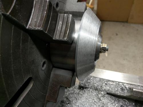
I removed the vertical attachment from the mill- hopefully for the last time as the J-head graft is (I hope) my next project- and got the dividing head set up to 45 degree tilt and centred on the involute cutter
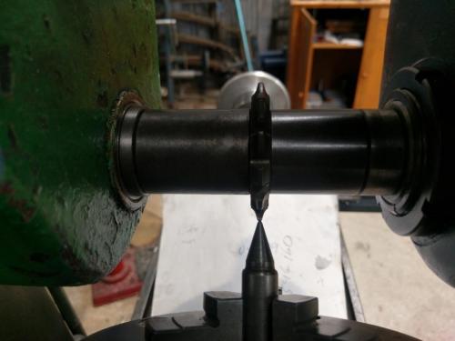
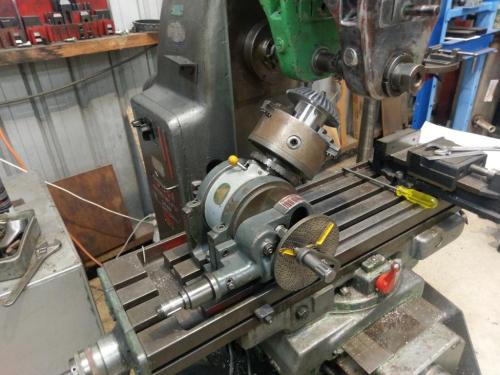
The 40-tooth gear happily took away one of the dividing tasks as my dividing head is 40:1 so, one revolution of the handle per tooth and back to the same hole. Bevel gear teeth are cut in 3 passes; one cut down the centre, then the table is stepped across half the pitch distance and the dividing head rotated half the index angle and a second cut is made, the cutter enters the cut through the same gap that it cut previously but then cuts a tapered path toward the heel. For the third pass, the setup is stepped across the same way in the opposite direction and the other side of the tooth gap is cut. This results in the tooth gap having a matching taper to the tooth. Apparently you can delete the first, central cut and do it in two passes but the book I was using recommended three passes. That's 120 cuts per gear.
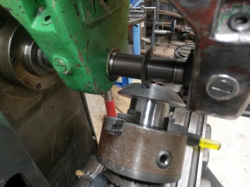
First cut:
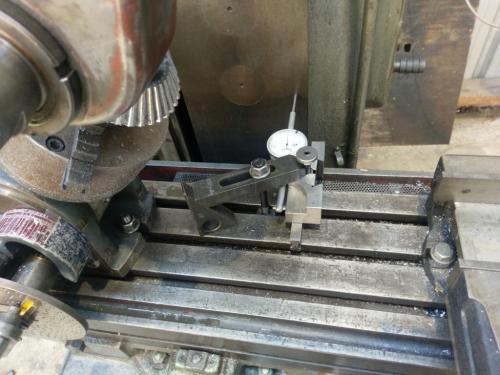
Used my poor-man's DRO to step the table across accurately between cuts
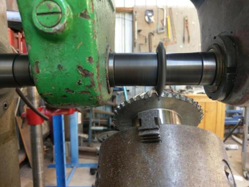
Final cut (one gear) three hours later:
The second gear was cut from a piece of aluminium plate stock of unknown grade that I had lying around, just large enough to have the gear blank hidden inside it. The cast blank was nicer to machine than this piece of stock, end result was much the same though. I sped up the X-feed slightly for the second and third passes on this gear, took only 45 minutes for the 40 cuts rather than an hour. I've already posted a photo of the gears but here they are again
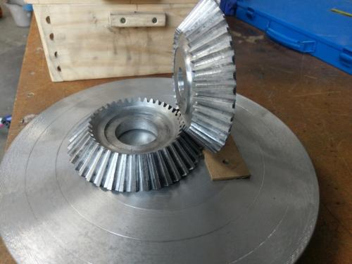
Yes that is the throwing head they are sitting on, I've got some photos of that to put up next time I get a chance to post.
Setting it up as a mockup, I discovered that when pedalling, the side uprights were too restrictive. Decided they weren't structurally necessary so cut them off and left just the two rear uprights supporting the top frame, also shortened the top horizontal frame back to the first cross-member to mount a P-type bearing block instead of the flange mount. The flange-mount bearing in the photo above sits on the bottom frame and bears the flywheel weight axially.
I don't have any sheet-metal equipment so I had to get a local business to do the folding and rolling for the tray, got them to make a 3-sided tray 400mm wide and 100mm deep, plus roll a 100mm-wide strip to a 400mm radius, and roll an arch out of a length of 16mm round bar which would become the rim of the tray, better arm rest than a sheet-metal edge. Spent a while cutting and shutting and ended up with this
I welded four 8mm bolts to the underside so no drilling would be needed once it was galvanised. The two bits of tubing- one for a riser around the main drive shaft and the other tapered piece to put a drain hose on- were salvaged from the bicycle frame.
Spent a morning taking it to the galvanizing mob. I was hoping to get a look at the galvanizing process but they are a big operation with lots of things like building frames coming and going, oversize forklifts busy everywhere, I was pleased to get in and out without getting run over.
I phoned them before taking the drive to discuss where I would need holes for hanging and draining. I had made a drain hose spout in the bottom of the tray, with a little more forethought I could have positioned this where it would have worked as a zinc drain for the dipping process. I had to drill a hole in one of the bottom corners and another just under the rim opposite, need to bog these up later. Picked the finished tray up from the galvanizers last Thursday; a bit of distortion but not a problem and I don't reckon it will rust away in a hurry.
I got on with figuring out the drive mechanism in the meantime, the vertical rotation of the pedals is converted to horizontal rotation of the flywheel and throwing head by a pair of bevel gears. I've never cut gears before, I've gathered some equipment in preparation for making a couple of missing change gears for my lathe but have not got around to doing any yet. I was a bit taken aback by just how complicated bevel gears are. To make the drive mechanism with the gears and the bicycle hub work, I had to make the bevel gears a specific diameter (5 1/2") at the large end so that the bicycle hub would clear the vertical drive shaft. Unfortunately, all the calculations for bevel gears are based on the diameter of the small inner end. I spent about 3 hours making calculations and entering them into an online gear calculator until I came up with a 40-tooth 12DP 45 degree bevel gear 1 inch thick which would (a) give me the 5 1/2" large diameter and (b) use an involute gear cutter that I already had. Bevel gears don't even use a sensible gear cutter, you use a cutter for a number of teeth on some theoretical, non-existent gear based on the pitch circle of your bevel gear multiplied by some kind of voodoo spell. Anyway, I had the appropriate cutter so happy days.
I whittled away at the round lump of a casting until I had a gear blank of the appropriate dimensions. Made an arbor to mount the blanks in the lathe and in the dividing head, the two gears have different bores so the arbor is double-ended with a 25mm spigot one end and 37mm (diameter of the appropriate part of the bicycle hub) the other end.
I removed the vertical attachment from the mill- hopefully for the last time as the J-head graft is (I hope) my next project- and got the dividing head set up to 45 degree tilt and centred on the involute cutter
The 40-tooth gear happily took away one of the dividing tasks as my dividing head is 40:1 so, one revolution of the handle per tooth and back to the same hole. Bevel gear teeth are cut in 3 passes; one cut down the centre, then the table is stepped across half the pitch distance and the dividing head rotated half the index angle and a second cut is made, the cutter enters the cut through the same gap that it cut previously but then cuts a tapered path toward the heel. For the third pass, the setup is stepped across the same way in the opposite direction and the other side of the tooth gap is cut. This results in the tooth gap having a matching taper to the tooth. Apparently you can delete the first, central cut and do it in two passes but the book I was using recommended three passes. That's 120 cuts per gear.
First cut:
Used my poor-man's DRO to step the table across accurately between cuts
Final cut (one gear) three hours later:
The second gear was cut from a piece of aluminium plate stock of unknown grade that I had lying around, just large enough to have the gear blank hidden inside it. The cast blank was nicer to machine than this piece of stock, end result was much the same though. I sped up the X-feed slightly for the second and third passes on this gear, took only 45 minutes for the 40 cuts rather than an hour. I've already posted a photo of the gears but here they are again
Yes that is the throwing head they are sitting on, I've got some photos of that to put up next time I get a chance to post.
Lathe (n); a machine tool used in the production of milling machine components.
Milling Machine (n); a machine tool used in the production of lathe components.
Milling Machine (n); a machine tool used in the production of lathe components.


