Posts: 4,683
Threads: 93
Joined: Feb 2012
Location: Perth, Australia
The following 1 user Likes Mayhem's post:
oldgoaly (08-14-2013)
10-18-2012, 09:43 AM
(This post was last modified: 10-19-2012, 06:40 AM by Mayhem.)
Some of you have seen pictures and info regarding my lathe but I have never really posted about her history or the work that I have done and will continue to do. There are several of post on some other sites but nothing that really puts it all together. A lot of those posts were questions about what or how to do something, and some ran their course, some died and some never really got going.
As this is the web site that I spend 99% of my time on, I decided I would put together a thread that outlines what I have done thus far. This will be a long, image intensive thread, as it will contain everything where on other sites it was split over several threads and punctuated with responses from other members.
So grab a drink  , something to snack on  , make yourself comfortable and we shall begin.
Once upon a time, in a land far, far away...
Hunting American dentists since 2015.
Posts: 4,683
Threads: 93
Joined: Feb 2012
Location: Perth, Australia
The following 1 user Likes Mayhem's post:
oldgoaly (08-14-2013)
10-18-2012, 09:49 AM
(This post was last modified: 10-20-2012, 11:29 PM by Mayhem.)
I had been interested in getting one for some time but they are few and far between here, and when they do come up they are well out of my price range. As it happened, I wasn't actually "looking" when I saw the add in a local classified. It simply read Metal lathe. large. 3 phase.
The add was correct - It was BIG! The overall length is 9' 10", height is 8' 10" and it needs 4' 10" to accommodate the depth. It has a 10" 3-jaw chuck and a 16 4-jaw. The spindle through hole is approximately 3" and the bed is 5' long. She swings 18 over the ways and 36 in the gap, and was designed for an overhead line shaft and had been converted to run with a 40 Hz 440V 4HP motor.
Note the 16" 4-jaw chuck and change gears on the ground
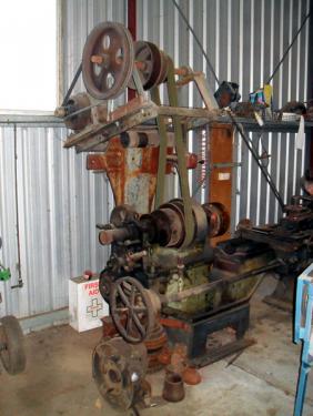
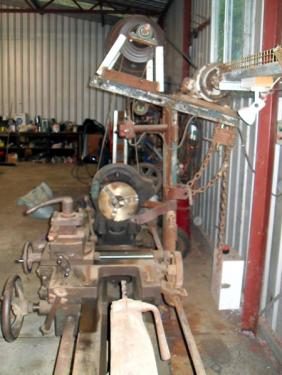
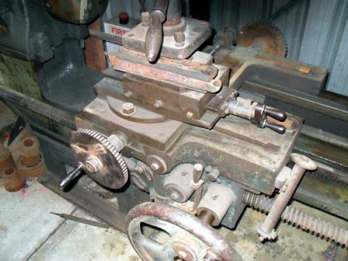
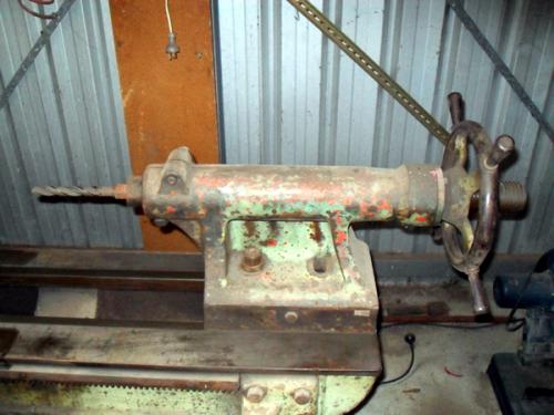
I had no idea as to the make, model or age. The previous owner had no idea either. There were no name plates, stampings or other marks that would indicate its origins. It was in need of a good clean up and needed some work, as there were a few bits missing that are required to get the auto feeds working. I took a mate of mine (who is a machinist) along with me to look at it, as I was actually thinking of walking away. Good that I took him, otherwise this would be a very brief thread.
I bought her at the end of October 2010, so I have had her from 2 years now. It took about 12 months to get her cleaned up and running, spending only Saturday's working on her. Whilst I have made good progress, I still have plenty to do.
I posted this info and a few pictures on some other sites (as this one didnt exist back then) to see if anyone could help identify it. I was directed to lathes.co.uk and contacted the owner for his thoughts and comments. Whilst he hadnt seen anything like it, he suggested that it was built sometime between 1895 and 1910.
I received a PM from a member on one of the sites that I posted on, who had a similar lathe. His is larger and a little more modern but there are too many similarities for it to have been made by a different company. His research had also failed to turn up a definitive answer but he had learned that some of the larger mining companies here in Western Australia made their own engines and other machinery. Some other early companies may also have done so.
Hunting American dentists since 2015.
Posts: 4,683
Threads: 93
Joined: Feb 2012
Location: Perth, Australia
The following 2 users Like Mayhem's post:
oldgoaly (08-14-2013), kenne (06-28-2014)
10-18-2012, 09:56 AM
(This post was last modified: 10-20-2012, 11:30 PM by Mayhem.)
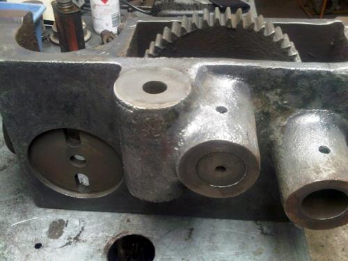
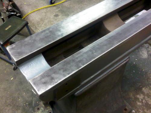
Once delivered, I began the slow process striping her down, cleaning her up and putting her back together. As you would expect for her age, there was a heap of grease, oil, chips, varnish, several layers of paint and some surface rust (fortunately nothing on the ways and other critical surfaces).
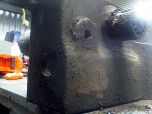
Rear of the apron
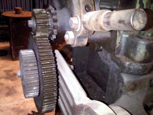
Tumbler, banjo, change gears
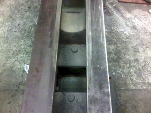
Ways (looking towards the headstock)
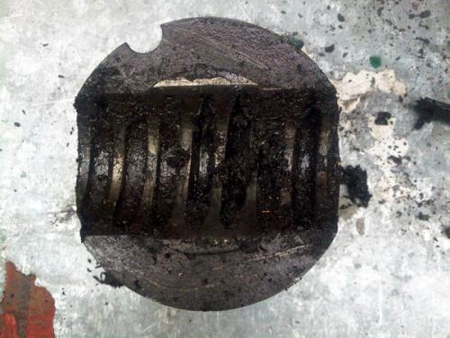
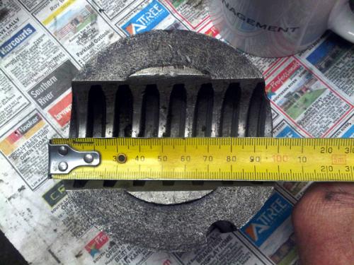
There were some through holes that when viewed from the bottom, looked as if they were blind. It wasnt until I dug chips out of the top and revealed a thread that I made a thread chaser to suit and noticed it pushing out chips from the bottom. The chips were that tightly packed in there that the plug that came out actually had a countersunk head!!!! The half nuts are massive heavy things that are about 6 x 5.
Half nuts!
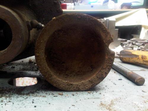
After cleaning
Apron looking a little more presentable
Ways after cleaning
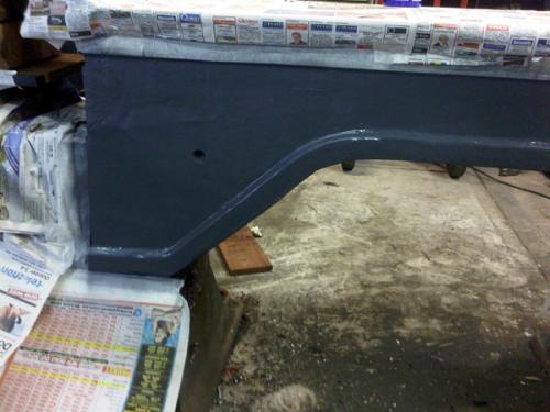
Given her age and the subsequent inherent flaws in some of the castings, I decided that I didnt want to try and give it a perfectly flat, show room finish as I think it would look out of place. As such, I cleaned her down to bare metal where needed and primed and painted. There were a number of different colours on the lathe and it looked like the saddle/apron were originally blue but the rest was either blue or the pale green. I decided on blue in a hammer tone finish. I polished the hand wheel rim and handles but there are pits in them which will never come out and I think they add character.
Paint
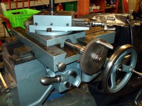
The cross slide wheel hub had broken off and previously been welded on, as had the break in the wheel. Problem was that they had been mig welded, with normal wire and were weak. The chuck adaptor for the 3-jaw chuck was, in fact, a back plate SPOT welded to the chuck adaptor for the 4-jaw. This needed to be rectified, as those welds could let go at any time!
Note the battle scars!

A back plate welded to a chuck adaptor!!
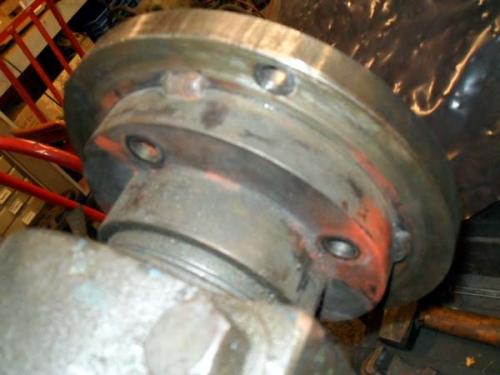
Hunting American dentists since 2015.
Posts: 4,683
Threads: 93
Joined: Feb 2012
Location: Perth, Australia
10-18-2012, 10:27 AM
(This post was last modified: 10-20-2012, 11:31 PM by Mayhem.)
So, since I was unable to use the 3-jaw, I removed it from the backing plate and then fabricated a quick and dirty wrench to try to remove the chuck adaptor (as I didnt have any luck with the chuck in place). Finally, with the help of a long cheater bar, it came off.
Wrench
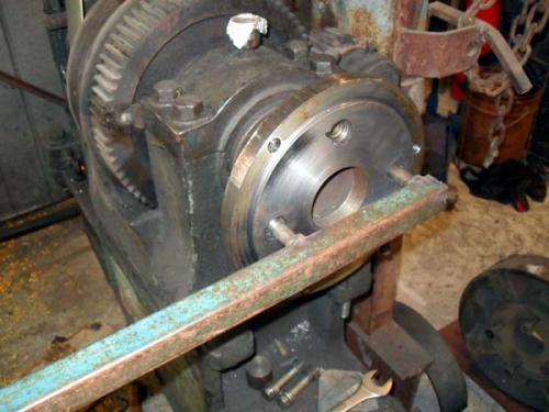
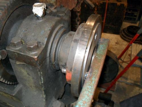
4" spindle nose, 6tpi
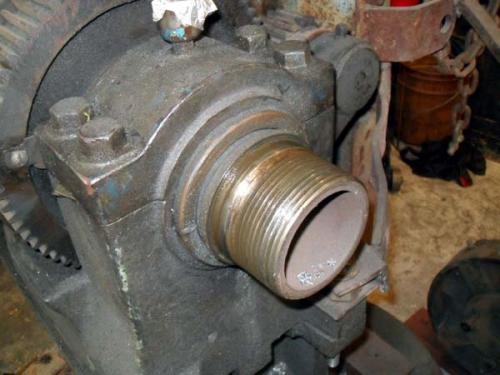
Next, I set about cleaning up the 4-jaw chuck and discovered it was made by Roto-Record in Germany. It took a while to clean up and there was that much dirt in the back that I wonder if it was buried at one point!
Ready for cleaning
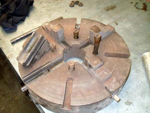
1/4 done - only 3 more to go
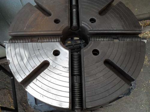
Finished the face and can actually see a makers name!
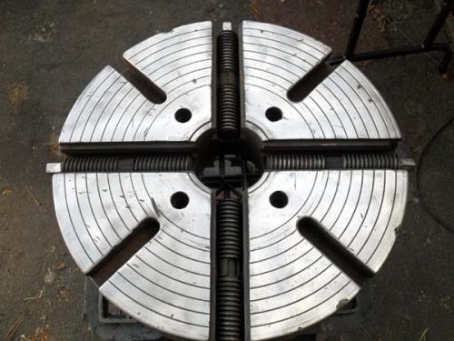
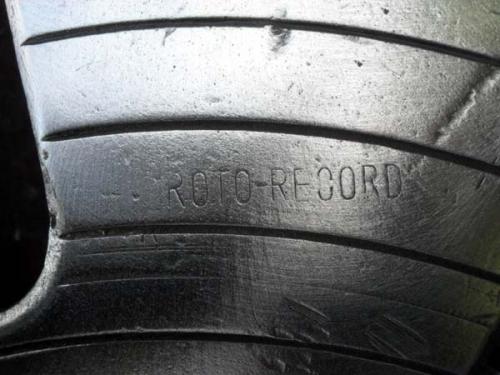
And here I was thinking I was the only one who occasionally held a stamp the wrong way
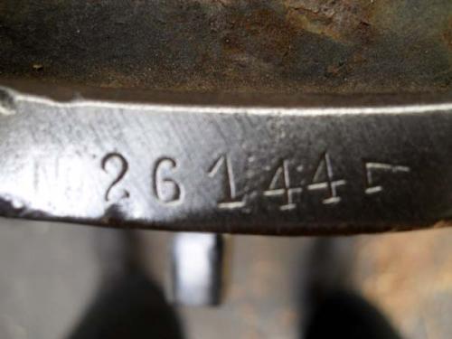
I did say it looked like it had been buried!
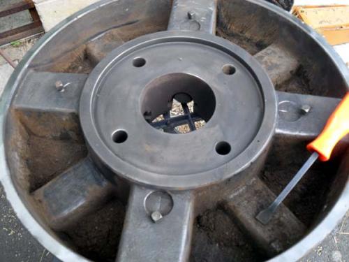
All finsihed. That isn't paint either, I oiled it with Balistol
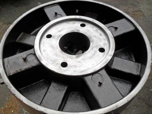
Once it was cleaned and oiled I placed the backing plate in the freezer overnight and then left the chuck in the sun all day before placing the backing plate into the recess and aligning the mating marks. Whilst I still havent made a backing pate to fit the 3-jaw, I can grip it in the 4-jaw if needed. The only problem with the 4-jaw is that I cant hold anything smaller than 2 diameter.
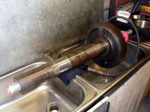
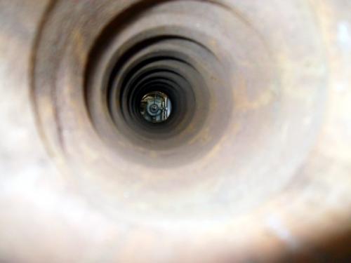
With the chuck off, I was able to remove the spindle from the headstock and inspect the bearings. As expected, these were white metal bearings and from what I could gather, they weren't all that bad given their age. The spindle is about 36 long and the through hole at the front is a little over 3 and a little under 3 and the end. It has a nice internal spiral running through it as well.
Spindle out of lathe and into a cradle I made to hold it
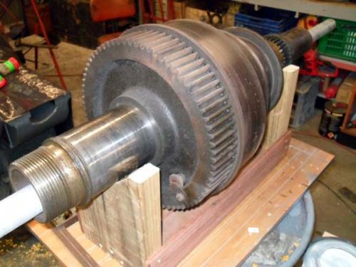
Everything but the bull gear removed and in (on) the parts cleaner
View through the spindle (from rear)
White metal bearings on a bronze shell
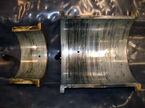
Hunting American dentists since 2015.
Posts: 4,683
Threads: 93
Joined: Feb 2012
Location: Perth, Australia
The following 1 user Likes Mayhem's post:
oldgoaly (08-14-2013)
10-18-2012, 11:00 AM
(This post was last modified: 10-20-2012, 11:31 PM by Mayhem.)
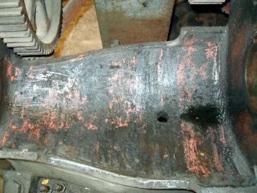
Few more pics of the headstock stripped down:
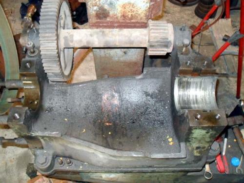
WTF? who would paint it pink?
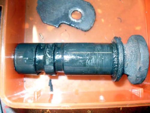
This is the bull gear locking pin (before and after). Originally I thought this would have been a ball and spring detent. So I found a few different size balls and they would either fall out or bind. I couldn't get a spring to stay in either. Then, hidden beneath 100+ years of crud, I found a threaded hole for a setscrew on the rear of the gear. I found a suitable setscrew and shaped the end so it would fit the groove. It worked OK but needed some resistance. I later noticed a v-groove in the bull gear and I found an old leather key ring and cut of a slither with a square cross-section to match the groove. This provides enough resistance and the pin works like a charm now.
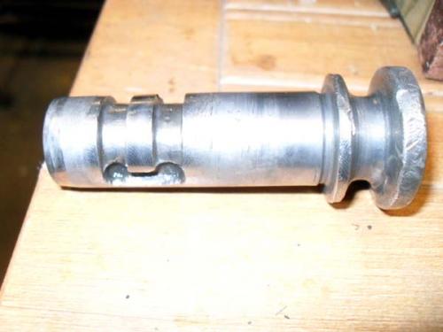
Bad picture but if squint just right you can see the v-groove at 6 o'clock
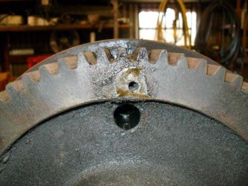
Hunting American dentists since 2015.
Posts: 4,683
Threads: 93
Joined: Feb 2012
Location: Perth, Australia
10-18-2012, 11:16 AM
(This post was last modified: 10-20-2012, 11:32 PM by Mayhem.)
The next step was to remove the back gears, which initially was a bit challenging. I finally figured out that the inner shaft had to be removed from the front. To do this, the split bush at the front (which had spilt in two) had to be removed and then the shaft lined up with the casting holes, whilst gently coaxing the shaft with a copper hammer.
Back gears removed
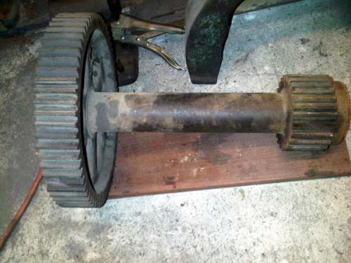
Here is a good shot of the eccentric shaft and the split bush
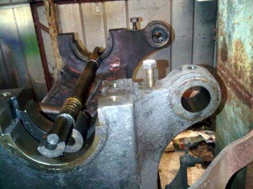
With, the back gears removed, the broken teeth could be fixed. There were also a few broken teeth on the bull gear, which I also fixed. Many of the teeth could be repaired simply by brazing the deficit and then filing to shape.
One tooth was missing most of the top and another had lost approximately ¾ of its width (full depth). The former was repaired by welding a steel rod the full length and for the latter I drilled and tapped some holes to suit some steel rod which I then filled in with braze. Again, they were hand finished with a file.
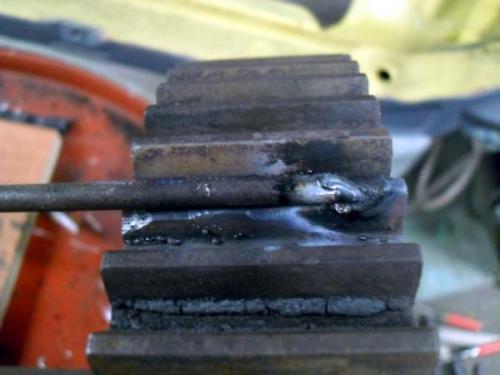
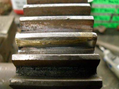
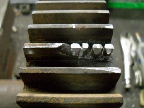
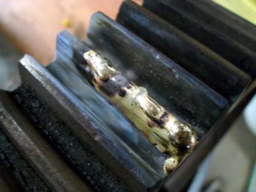
All fixed

Hunting American dentists since 2015.
Posts: 4,683
Threads: 93
Joined: Feb 2012
Location: Perth, Australia
10-18-2012, 11:49 AM
(This post was last modified: 10-20-2012, 11:32 PM by Mayhem.)
Now it was onto the spindle.
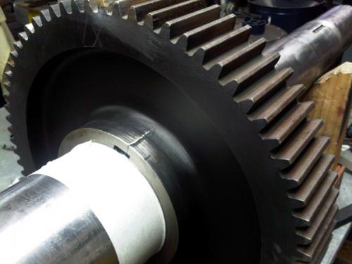
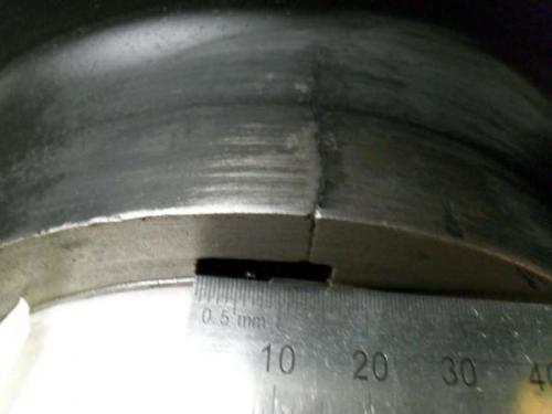
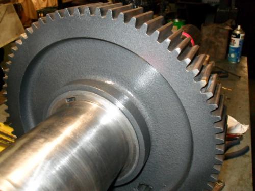
Once I had cleaned all the parts, I noticed that the bull gear had a crack in the hub, where the key inserted. I didn't want to try and weld this up, so I had it repaired by getting a steel ring machined and then shrink fitted over the hub. A hole was also drilled at the end of the crack to prevent it from cracking further.
The crack
The fix (and paint)!

Whilst this was being done, I was also working on cleaning the headstock and painting it and other associated parts.
Let the fun begin!
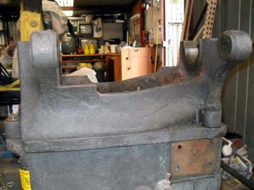
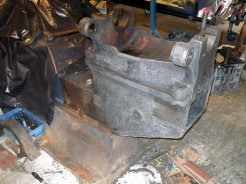
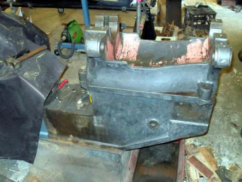
Primer
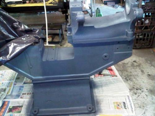
Top coat
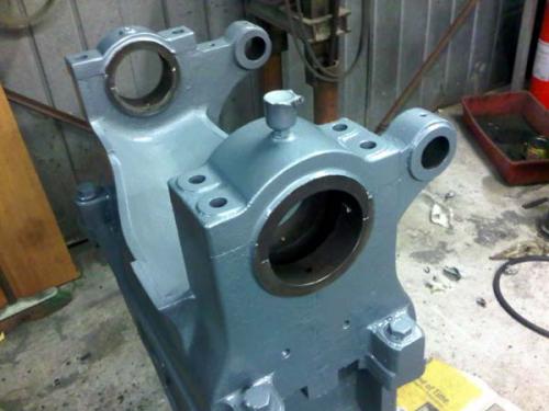
Did I mention I was going with a two-tone colour scheme?
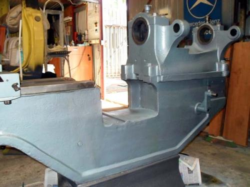
Starting to look like a lathe again
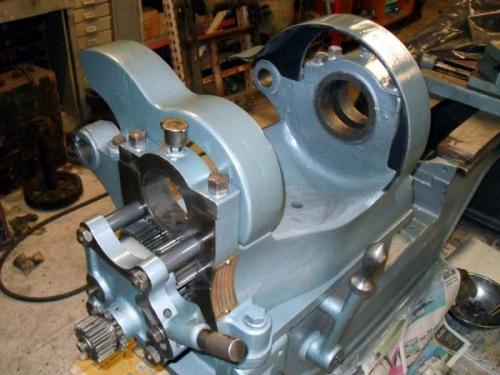
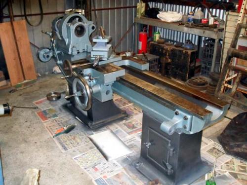
Hunting American dentists since 2015.
Posts: 4,683
Threads: 93
Joined: Feb 2012
Location: Perth, Australia
10-18-2012, 12:01 PM
(This post was last modified: 10-20-2012, 11:33 PM by Mayhem.)
The cone pulleys were cleaned up, greased and the spindle reassembled.
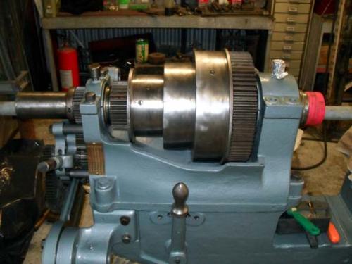
The next step was to shim the bearings and set the end play. I didn't take any pictures of the new shims but here is one of the old ones. Each shim is the same shape as the cross-section of the bearing.
Rear bearing
 20110108-028.JPG
 (Size: 22.27 KB / Downloads: 529)
From memory, the gap between the shim and the journal is for a reason but I cannot remember it right now. I know that I did try using a shim that was rectangular, rather than the cross-section shape and the caps wouldn't seat correctly.
In this picture, I have coloured the shim red and the gap white (front bearing)
 20110108-026x.JPG
 (Size: 21.3 KB / Downloads: 525)
Without the shims, the bearing cap will lock the spindle.
I cut new bearings shims and set the bearings to have between .001 and .002 play (front and rear), and set the end play to .001 as outlined in the old South Bend literature (its all I had to work off). I run these with plenty of oil!
Hunting American dentists since 2015.
Posts: 4,683
Threads: 93
Joined: Feb 2012
Location: Perth, Australia
10-18-2012, 08:24 PM
(This post was last modified: 10-20-2012, 11:34 PM by Mayhem.)
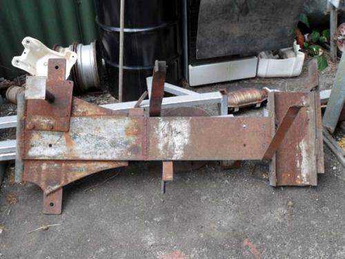
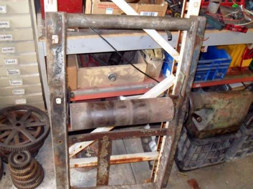
With the lathe reassembled, I needed to redesign the motor mount as I wasn't happy with the current set up. The motor and the line shaft were set up so that the weight of the motor kept tension on the drive belt. However, this was unbalanced and use to rock, which in turn, caused the lathe to rock!
Anyone want a see-saw?
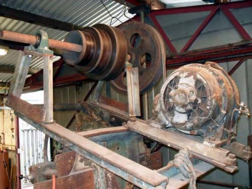
Note the counter-weights
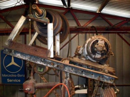
Attached to the lathe
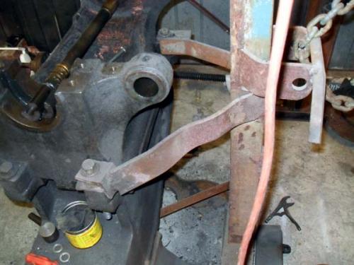
Note the extremely small footprint!
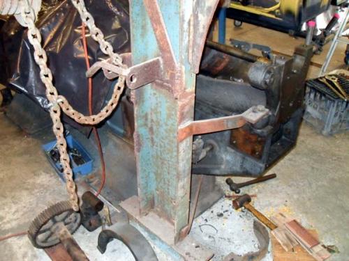
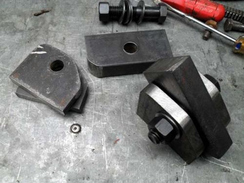
So I decided to mount the motor as close to the floor as possible and line shaft as low as possible without the belt fouling the back gears. I welded up some hinges using ½ plate and some think bar stock and built a frame around this.
Hinge components
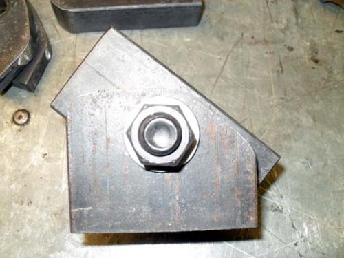
The shape ensures that the frame cannot tip too far away from the mill
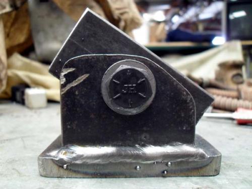
Welded onto 1/2" pads
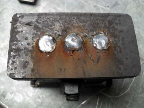
Top pads were plug welded to ensure that the pivot was not fowled in any way
With these finished, I made up a base that would not only support the drive assembly but will eventually accommodate a splash back/chip pan, and a guard for the back gears.
Hinges tacked into place and the drive assembly frame tacked on to the hinges.
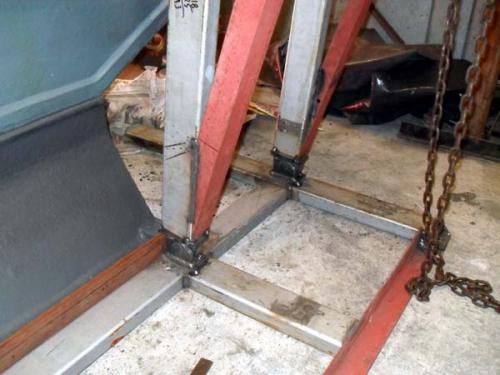
This puts it into perspective
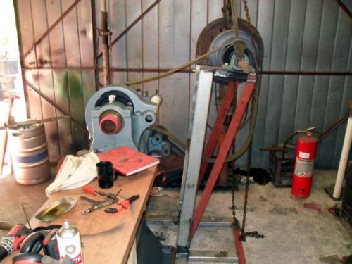
I welded in some braces, which added rigidity and also enabled the motor rails to be fitted. I then finished welding the places that had only been tacked.
Time for a lick of paint
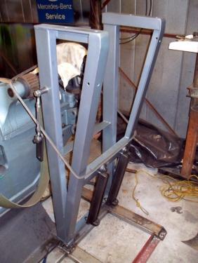
Hunting American dentists since 2015.
Posts: 4,683
Threads: 93
Joined: Feb 2012
Location: Perth, Australia
The following 1 user Likes Mayhem's post:
oldgoaly (08-14-2013)
10-18-2012, 08:41 PM
(This post was last modified: 10-20-2012, 11:35 PM by Mayhem.)
The motor sits as low as I could get it to, which was governed somewhat by the length of the v-belts I could buy off of the shelf. The purple spanset was used to hoist the motor into position so I could bolt it in place. The electrical cover was later found and put into place.
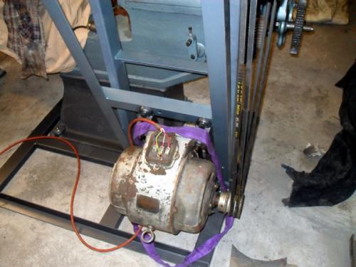
One of the (many) issues with the previous drive assembly was the inability to lock it into position. Instead, the weight of the motor (and anything else you wanted to hang off it) maintained belt tension.
I decided to make an over centre lock to keep tension on the newly shortened belt. I used a turn-buckle to enable fine adjustment and I am quite happy with the results.
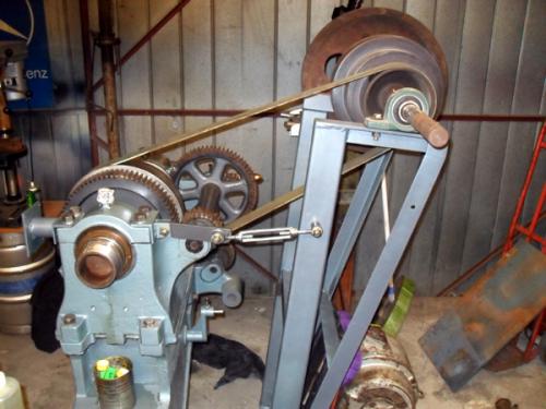
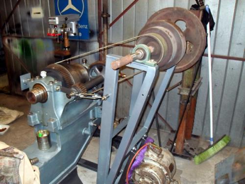
However, I plan to rework the lock to incorporate a handle to make it easier to change speeds.
Now that everything lines up nicely, it is time to remove the upper cone pulleys and the shaft, so they too can be cleaned.

Quick scrub and a lick of paint later
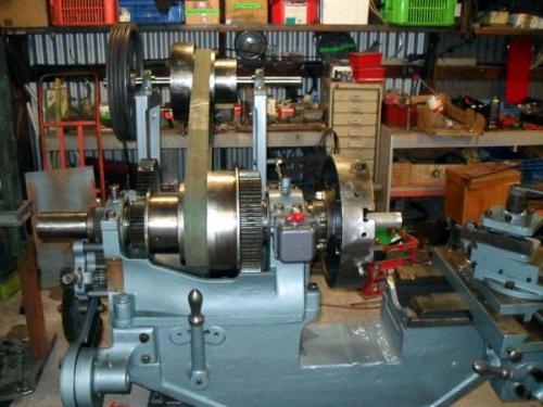
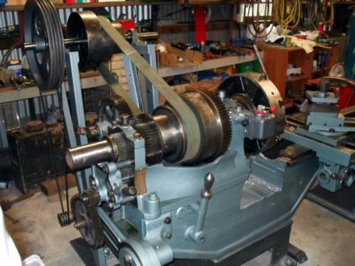
You will notice in the last two pics that I have relocated the drum switch to the front of the headstock. You may not have noticed earlier that this was originally mounted to the upright for the old drive assembly.
What of the old assembly? I hear you ask... Well it has since been weighed in for scrap
Hunting American dentists since 2015.
|
 , something to snack on
  , make yourself comfortable and we shall begin.
 , something to snack on
  , make yourself comfortable and we shall begin.


