03-25-2014, 10:52 PM
My Swedish Storebro lathe was set up for metric threading, although it has a 4 tpi leadscrew and QCGB settings for "English" threads. It never had a threading dial - no mounting holes or other indications of one. Since I do more standard threads than metric, I decided to make one.
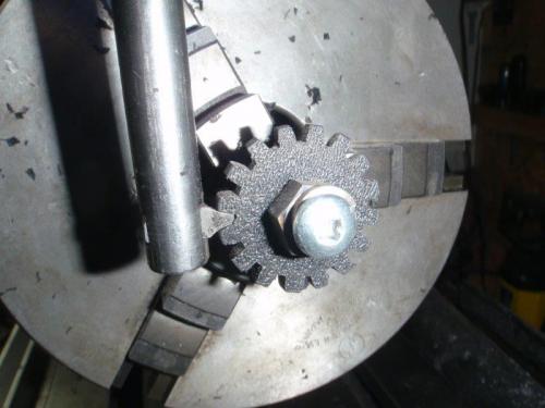
A week or two ago, I made up the gear to follow the leadscrew out of ABS.
I was going to make the body out of cast iron. I cut down a piece of scrap on the bandsaw.
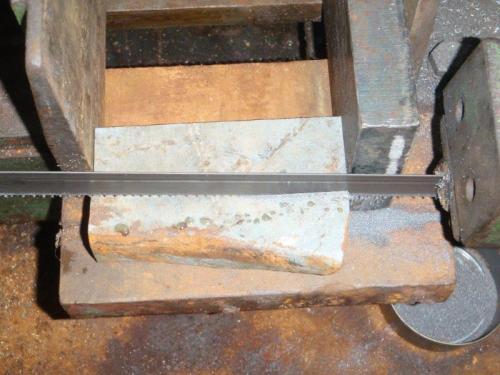
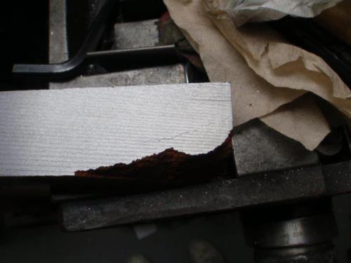
Unfortunately, close inspection revealed a crack, so it was rejected.
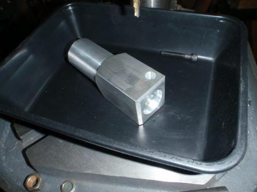
Plan B was an aluminum body, cut down, squared, turned, drilled and bored. I left it square to match the styling of the Storebro.
The dial spindle was turned down from a piece of steel bar. 1" dial, 3/8" shaft, 5/16" x 24 thread to hold the gear. The eight notches were scored with a marking rig I made a couple of years ago, then the four quadrants stamped.
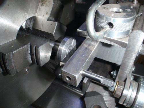
After assembly, the threading dial was mounted on the carriage. That's right, on the left side. This lathe has an apron layout that's the reverse of what most of us are used to. There was no easy way to mount it over the handwheel hub and oilers, plus, since the half-nut lever is on the left side, it made sense to have the dial close to that.
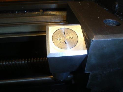
The down side of having the dial on the left is that it might conflict with the carriage stop. I designed the body to work around the stop.
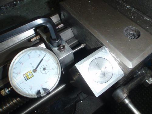
Shots of the gear engaged ...
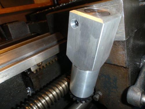
and disengaged.
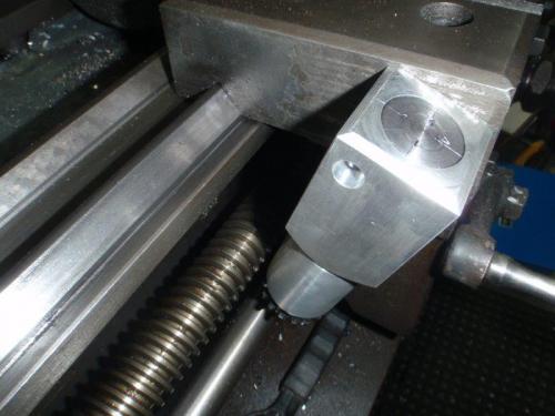
I should mention that you need to adjust the dial so that it aligns with the reference mark when the half-nuts are closed.
A week or two ago, I made up the gear to follow the leadscrew out of ABS.
I was going to make the body out of cast iron. I cut down a piece of scrap on the bandsaw.
Unfortunately, close inspection revealed a crack, so it was rejected.
Plan B was an aluminum body, cut down, squared, turned, drilled and bored. I left it square to match the styling of the Storebro.
The dial spindle was turned down from a piece of steel bar. 1" dial, 3/8" shaft, 5/16" x 24 thread to hold the gear. The eight notches were scored with a marking rig I made a couple of years ago, then the four quadrants stamped.
After assembly, the threading dial was mounted on the carriage. That's right, on the left side. This lathe has an apron layout that's the reverse of what most of us are used to. There was no easy way to mount it over the handwheel hub and oilers, plus, since the half-nut lever is on the left side, it made sense to have the dial close to that.
The down side of having the dial on the left is that it might conflict with the carriage stop. I designed the body to work around the stop.
Shots of the gear engaged ...
and disengaged.
I should mention that you need to adjust the dial so that it aligns with the reference mark when the half-nuts are closed.
Mike
If you can't get one, make one.
Hawkeye, proud to be a member of MetalworkingFun Forum since Jan 2013.
If you can't get one, make one.
Hawkeye, proud to be a member of MetalworkingFun Forum since Jan 2013.


![[Image: TomsTechLogo-Profile.png]](http://tomstechniques.com/wp-content/uploads/2013/11/TomsTechLogo-Profile.png)
