Digital Tachometer Problems
#1
I ordered a Chinese digital tachometer to use on my mini mill (DT-2234C+).  It had a lot of good press and it was cheap, so I figured I'd try it.  I thought I would use it to mark RPMs by the hundreds on the variable speed control dial.  This is it:
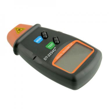
     

Well, it lights up, a laser shoots out the front, but every reading is 0 RPMs.  This diminishes its worth considerably.  I was wondering if I am doing something wrong?  Does anybody have any experience with one of these?


Charles
Charles Spencer, proud to be a member of MetalworkingFun Forum since Aug 2014.
Reply
Thanks given by:
#2
Isn't there a reflector or something that goes on whatever you're trying to clock? Seems to me there should be.
Logan 200, Index 40H Mill, Boyer-Shultz 612 Surface Grinder, HF 4x6 Bandsaw, a shear with no name, ...
the nobucks boutique etsy shop  |  the nobucks boutique
Reply
Thanks given by:
#3
Vinny that is how the old strobe-o-scopes worked, you would get your reflector to look like it wasn't moving then read your strobe setting. Don't know how these new fangle ones work???
oldgoaly, proud to be a member of MetalworkingFun Forum since Jun 2013.
Reply
Thanks given by:
#4
(06-20-2015, 09:44 PM)Vinny Wrote: Isn't there a reflector or something that goes on whatever you're trying to clock?  Seems to me there should be.

I have 2 of them, it needs a piece of reflective tape on the outside edge of what you trying to get an RPM on. a piece on the flange on the lathe chuck, a piece on the mill quill or a piece on the drill press spindle. It will not work properly without the piece of reflective tape.
jack
Reply
Thanks given by:
#5
Vinny and Jack are correct. It needs a small piece of reflective tape and ideally, the part you are sticking the tape to should be painted black.

Also - the component being measured should be spinning Big Grin

You may also wish to consider adding one of these to your mini mill, as you would get immediate readings and not have to spend time marking out increments on the machine:

http://www.machtach.com/

Henry Arnold is a member here and there is a thread on these:

http://www.metalworkingfun.com/showthread.php?tid=1138
Hunting American dentists since 2015.
Reply
Thanks given by:
#6
I wrapped the spindle in non-reflective black cloth electrical tape and put a square of the reflector tape on it. I also tried different angles, speeds, and distances. The results were 0.. 0.. 0..
Charles Spencer, proud to be a member of MetalworkingFun Forum since Aug 2014.
Reply
Thanks given by:
#7
(06-21-2015, 08:02 AM)Charles Spencer Wrote: I wrapped the spindle in non-reflective black cloth electrical tape and put a square of the reflector tape on it.  I also tried different angles, speeds, and distances.  The results were 0.. 0.. 0..

That should work since that's how I use mine for my mill. I'll pull mine out and see if there's something needed beyond turning it on and aiming it. It's been a while since I've used it.

Ed
Reply
Thanks given by:
#8
I don't even bother with the black back ground, I just stab a square of tape on. Its within 6 rpm of the stated rpm of lathe speed chart.


Attached Files Thumbnail(s)
       
jack
Reply
Thanks given by:
#9
I'd contact the seller Charles.

Thanks Jack. My instructions said that a reflective background could influence the reading. Good to know that it doesn't. Unless that is the 6rpm variance ?
Hunting American dentists since 2015.
Reply
Thanks given by:
#10
On the lathe its about 6 rpm difference, from the charted rpm and the actual rpm. On the drill press, that has an optical encoder, for rpm readings for the VFD, still no black back ground, it varies from the encoder by about .1 rpm (one tenth of a rpm), basically its accurate enough for me.
jack
Reply
Thanks given by:


Users browsing this thread: 1 Guest(s)