Posts: 4
Threads: 1
Joined: Feb 2016
Location: AZ, USA
The following 1 user Likes rust_bucket's post:
JScott (03-01-2016)
I finally took the plunge and added a 3-axis mill to the herd. I found this Kondia Powermill for a reasonable price very close by.
I hired a local equipment mover to handle the dirty work. -That was money well spent!
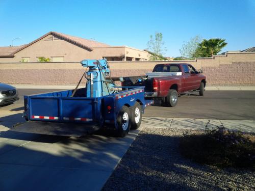
He pulled up with a hydraulic low-boy trailer and made it look so easy! He lassoed the pedestal and drug it onto the trailer.
He even put it exactly where I asked him to in the shop.
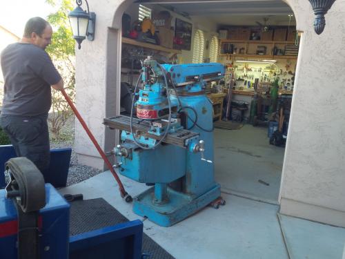
The ol' girl got a new paint job somewhere along the way. It's not just blue, it's: BLUE!!!!
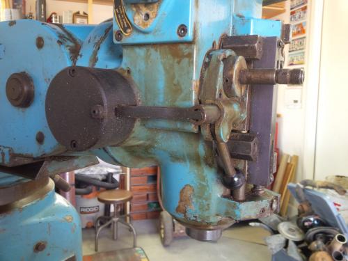
It took some elbow grease but cleaned up pretty good.
Before a scrub:
After:
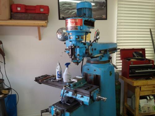
It's got an extra deep knee and ram kind of like a Lagun. The mover estimated it weighed around 2,700 lbs.
I'm in the process of going through it, mostly looking for neglected care and maintenance.
I was able to adjust the backlash down to 0.014" - 0.007" on the X and 0.011" -0.005" on the Y (at the ends vs. middle of the travel...) The wear seems to be pretty even on the gibs/ways. It only gets a little snug at the minimum Y position up near the column.
I'll post progress as I go along, and will of course ask the collective forum brain questions when I get stumped. (I already have one brewing, more to come...)
Rusty
Posts: 8,740
Threads: 313
Joined: Feb 2012
Location: Arizona/Minnesota
Nice score Rusty!
Oh, and  to the forum
Ed
Posts: 2,596
Threads: 99
Joined: Dec 2014
Location: Michigan
Posts: 432
Threads: 27
Joined: Feb 2016
Location: Woodstock:GA
02-26-2016, 11:05 PM
(This post was last modified: 02-26-2016, 11:47 PM by pepi.)
Very nice, that's one heavy duty looking machine.
Magazines have issues, everything else has problems
Posts: 4
Threads: 1
Joined: Feb 2016
Location: AZ, USA
Thanks fellas. I'm enjoying the forum. I just found it a few weeks ago.
So here's the issue I'm investigating: There's a little more noise in the spindle than seems right to me, so I figured I'd drop the spindle and have a look at the bearings. I'm a "mechanically minded person" but a total noob to 3-axis mill maintenance and repair. I watched a couple You-Tube videos of gents dropping spindles on Bridgeports. They show that all you need to do is remove the collet and draw-bar (obviously) then unscrew the nose cap and tap on the top end of the spindle with a brass bar and a mallet. The whole spindle drops right out of the quill without much trouble.
So, I spun a wrench on the lathe to twist off the nose-cap:
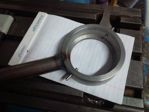
Twisted off the nose-cap:
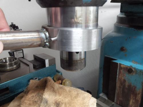
and proceeded to bonk on the top end of the spindle with a rod and mallet. It dropped a little over an inch easily, then seems to be held up. It doesn't feel like a burr or interference really, it's a fairly abrubt stop, like I forgot to move something out of the way.
In this picture you can see how far down it came. I believe the bottom ring there is the outside of the lower bearing, and the little bit of sleeve you can see still inside the quill is the spacer between the lower and middle bearing.
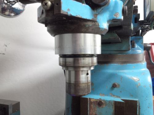
Can anyone comment on the subtleties of the Kondia spindle to quill interface and how it might differ from a Bridgeport?
I already touched base with Mayhem. He is going to send me some drawings that will hopefully shed some light on this subject.
Thanks gents!
Rusty
Posts: 4,683
Threads: 93
Joined: Feb 2012
Location: Perth, Australia
The following 1 user Likes Mayhem's post:
PixMan (02-27-2016)
Hi Rusty,
Your Kondia looks to be in good shape. All the handles that I can see appear to be the original ones and not busted off and replaced with welded on bolts. A much better specimen than mine was when I found her!
OK - now I understand your description in your PM. You are trying to drop the spindle, whilst leaving the quill in place. I actually dropped the whole quill assembly out and then removed the spindle. I can see that you have the R8 spindle, where mine has the NMTB30 spindle. However, the rest of the spindle is the same. Looking at the drawing (which I am about to email to you) the spindle should simply drop out.
I have a hydraulic press, so I decided that it was best to press the spindle out rather than hammer on it from above. I didn't want the rack on the quill to bust any gears from hammering. Although, you could use a block of wood to support the quill.
If you don't want to hammer away, it isn't a major job to drop the quill. You will need to remove the motor and the belt housing, so that you can remove the two screws at the top of the quill that engage the quill skirt. If you don't, you will break of the tabs on the quill skirt and you will need to make a new one, as a BP one will not fit. Not a major drama, as Kondia sent me the drawing. Also, you will need to remove the micrometer screw and the quill stop. Also, remove the quill feed lever, the spring will release once the rack disengages and you don't want that spinning around an smacking you. Of course, the quill lock will need to be loosened off too.
Overall, I think these mills are a lot more robust than the BP on which they were based and the good news is that many of the parts are still available from Kondia in Spain, and I have a contact there who is very helpful. When parts are no longer available, they have sent me the drawing so that I can get the parts made or make them myself. Thanks to PixMan, I have a custom feed trip bracket on mine. Out of interest, what year is yours? Mine is either 1969 or 1970 (based on the S/N), which places it amongst the first generation, many of which were 'hand finished'. I've certainly had to massage a few parts to get them to fit and function properly.
To be honest, I don't mind the blue...
A few emails will find their way to your in box very shortly 
Hunting American dentists since 2015.
Posts: 4
Threads: 1
Joined: Feb 2016
Location: AZ, USA
The following 1 user Likes rust_bucket's post:
Mayhem (02-28-2016)
02-28-2016, 12:25 AM
(This post was last modified: 02-28-2016, 12:36 AM by rust_bucket.
Edit Reason: typo
)
Mayhem, Thanks for all the info! It is a huge help. I don't know when it was manufactured. The plate on the front says 676 but the front right corner of the knee has 456 stamped in it.
I'm unsure if they mixed S/N's from the factory, or if this machine had a head transplant at some point...
I held my breath and just pounded a little harder on the spindle and sure enough, it dropped out the bottom of the quill. I found the upper bearing in perfect working order and the lower two bearings to be ever so slightly rough. They weren't loud at all, they just weren't perfectly smooth. I think I will still replace all three of them for good measure. No sense in getting a few months down the road and needing to tear back into it. They definitely weren't the source of the noise while running however, so I had to dig a little deeper.
I pulled off the motor and the belt housing and it was easy to diagnose, the upper pair of bearings inside the step pulley axle are SHOT! The lower pair, still buried inside the head don't sound wonderful, but certainly aren't as bad. I think I will just swallow the bitter pill now and replace all 7 on the spindle assembly and the two on the back gear. The only spendy ones are the matched pair 7207's at the business end of the quill. I'll have to hunt around for a decent price on those...
Posts: 2,596
Threads: 99
Joined: Dec 2014
Location: Michigan
The following 3 users Like Vinny's post:
Mayhem (02-28-2016), EdK (02-28-2016), f350ca (02-28-2016)
Rusty, are you using a stethoscope to track down the source of the noise? If not I recommend it. Whether you use an actual stethoscope or just a long screwdriver pressed against your ear, it's the best way to track down a noise source.
Posts: 4
Threads: 1
Joined: Feb 2016
Location: AZ, USA
The following 2 users Like rust_bucket's post:
f350ca (03-11-2016), Mayhem (03-11-2016)
The stethoscope sounds like a good trick. I'll have to try that out!
I made some more progress on the ol Kondia last night. I think Ive spent more time building tools than actually working on the machine. Id be nearly $150 into spanner wrenches by now if I went out and bought what I needed. But with a lathe, a welder and drill press, Ive managed to get the job done with some scraps of steel and some time.
The most elaborate was this one for pulling the back-gear. I was afraid to just throw a puller on there because it would only engage on 2 teeth, so I cut this ring and welded a few off-set tabs so it can come apart and still be flush on top. It worked like a charm.
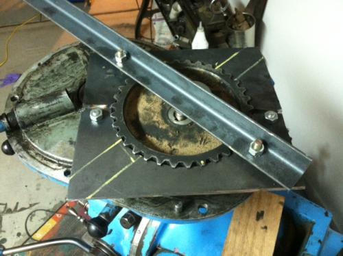
 plate removed.JPG
 (Size: 46.37 KB / Downloads: 54)
At this point I have the upper bearing assembly all the way apart and the back-gear assembly apart.
 upper assy.JPG
 (Size: 36.39 KB / Downloads: 54)
New bearings are in-hand. I could only find ZZ bearings, but the upper assembly calls for a single shield and the back-gear bearings are full open. So I just de-Zd them as necessary. J
 DeZ1.JPG
 (Size: 28.54 KB / Downloads: 54)
 DeZ2.JPG
 (Size: 27.41 KB / Downloads: 54)
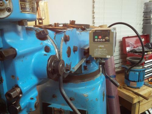
I also got the VFD re-mounted on the front side of the machine. The previous owner had it mounted on the back of the machine for some inexplicable reason. Since I have to use the VFD for starts and stops, it kinda needs to be readily accessible.
Posts: 8,740
Threads: 313
Joined: Feb 2012
Location: Arizona/Minnesota
(03-11-2016, 10:54 AM)rust_bucket Wrote: Since I have to use the VFD for starts and stops, it kinda needs to be readily accessible.
Connect a remote box with the switches and speed potentiometer. That way your expensive VFD doesn't get showered with swarf and go up in flames. 
Ed
|


 to the forum


