04-19-2016, 02:57 PM
I'm not sure if this is the right place for this. I suppose it could go in Projects or Metrology but since it is primarily used on milling machines I plopped it here.
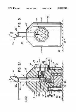
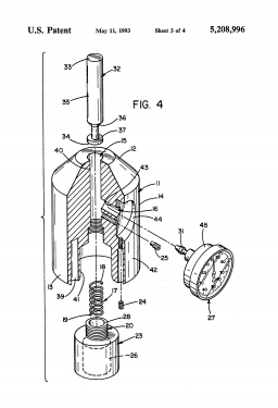
I was looking for a simple, inexpensive way to set a "zero" on the mill in the z-axis for those times when I want to get back where I started from. There are several models available for sale but none really floated my boat and they cost more than I want to spend. Searching the net I came across an expired patent for a version that uses a dial indicator and a vertical plunger in a solid body. It looked pretty simple to adapt to my needs so I made up a drawing of what my version will look like. I drew it up using a standard AGD 2 indicator like the one from Harbor Freight.
In operation the gauge plunger would be set at a height of exactly 3.000" and the dial indicator zeroed at that height. Then you place the gauge on top of the workpiece or vise and slowly lower the quill of the mill until it touchs the top of the plunger. The quill is lowered gradually until the dial indicator reads zero. At this point the tool in the spindle should be exactly 3.000" above the reference surface. The mill dial or DRO can be zeroed at this time and allow you to calculate the elevation where you want to start cutting.
I have some 2x2 blocks of 4140 pre-hard steel that should be perfect. The gauge could also be round but square is vise friendly. I did not add any magnets to the base because of the tendency to pick up chips. Also, I did not add any holes to make it lighter because I don't want the overhung load from the indicator to tip it over.
Please be advised that I have not fabricated this item yet but I do not see any glaring flaws in the design that will keep it from working. I don't know when I'll get to the build so I thought I would throw this out for review and discussion. Please respond with any comments or suggestions.
The commercial version. Very nice, but too expensive for me.
 Picture2.jpg (Size: 19.8 KB / Downloads: 107)
The patented version.


And my version.
 Zaxis gage Rev A-Model.pdf (Size: 106.01 KB / Downloads: 34)
I was looking for a simple, inexpensive way to set a "zero" on the mill in the z-axis for those times when I want to get back where I started from. There are several models available for sale but none really floated my boat and they cost more than I want to spend. Searching the net I came across an expired patent for a version that uses a dial indicator and a vertical plunger in a solid body. It looked pretty simple to adapt to my needs so I made up a drawing of what my version will look like. I drew it up using a standard AGD 2 indicator like the one from Harbor Freight.
In operation the gauge plunger would be set at a height of exactly 3.000" and the dial indicator zeroed at that height. Then you place the gauge on top of the workpiece or vise and slowly lower the quill of the mill until it touchs the top of the plunger. The quill is lowered gradually until the dial indicator reads zero. At this point the tool in the spindle should be exactly 3.000" above the reference surface. The mill dial or DRO can be zeroed at this time and allow you to calculate the elevation where you want to start cutting.
I have some 2x2 blocks of 4140 pre-hard steel that should be perfect. The gauge could also be round but square is vise friendly. I did not add any magnets to the base because of the tendency to pick up chips. Also, I did not add any holes to make it lighter because I don't want the overhung load from the indicator to tip it over.
Please be advised that I have not fabricated this item yet but I do not see any glaring flaws in the design that will keep it from working. I don't know when I'll get to the build so I thought I would throw this out for review and discussion. Please respond with any comments or suggestions.
The commercial version. Very nice, but too expensive for me.
 Picture2.jpg (Size: 19.8 KB / Downloads: 107)
The patented version.
And my version.
 Zaxis gage Rev A-Model.pdf (Size: 106.01 KB / Downloads: 34)
JScott, proud to be a member of MetalworkingFun Forum since Mar 2014.


![[Image: TomsTechLogo-Profile.png]](http://tomstechniques.com/wp-content/uploads/2013/11/TomsTechLogo-Profile.png)
