Posts: 4
Threads: 1
Joined: Sep 2013
Location: Australia
(12-01-2012, 09:20 PM)Mayhem Wrote: I had posted about this lathe over on the PM site when I first got her, hoping that someone may be able to provide some information on her heritage.
Yesterday I received an email notification of a new reply and it seems there is another Australian out there with a similar lathe. What was more interesting was that he referred to his as a "Willson" lathe.
This morning, I see there has been another reply, this time with a link to some info on the Willson from www.lathes.co.uk Whilst there is only 1 photo of the lathe, it does look like mine. Especially the bed and the tail stock. The nameplate appears to have been placed on the door of the headstock pedestal, which is missing from my lathe.
Here is the post on PM
Here is the page from lathe.co.uk
hi posted a message on the other site re SBWillson lathe in victoria John
JOHN.ASHBURN, proud to be a member of MetalworkingFun Forum since Sep 2013.
Posts: 2,685
Threads: 29
Joined: Feb 2012
Location: Nova Scotia, Canada
Busy Bee 12-36 lathe, Busy Bee Mill drill, Busy Bee 4x6 bandsaw, Homemade 9x17 bandsaw, Ad infinitum.
Posts: 537
Threads: 15
Joined: Jun 2012
Location: Cambridge, England
It's easy to do ;)
Whatever it is, do it today, Tomorrow may not be an option and regret outlasts fatigue.
Posts: 4,683
Threads: 93
Joined: Feb 2012
Location: Perth, Australia
09-05-2013, 08:49 PM
(This post was last modified: 09-05-2013, 08:53 PM by Mayhem.)
(09-04-2013, 07:18 PM)JOHN.ASHBURN Wrote: hi posted a message on the other site re SBWillson lathe in victoria John
Hi John,
Interesting - I don't remember reading that post (perhaps I deleted the email from PM).
I would really appreciate seeing any pictures that you have and if you were able to measure up the worm that rides on the power feed shaft that would be fantastic.
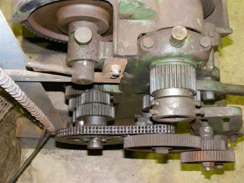
I've posted these before but it is easier to post them again. First up is the chain drive on a similar lathe up in the far North of WA, which I am basing my build upon (a lot of the parts are missing on mine)

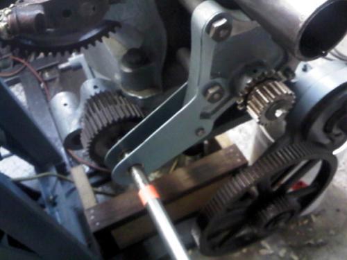
Here is my work so far. In this pic you can see the drive sprocket behind the spindle gear. The assembly immediately behind that is the tumbler reverse and the brackets I have made attach to this. The small bolt at the bottom screws into a 1" plug, which I made to sit in the hole that is in the lower left portion of the tumbler reverse casting. I believe that this may have been used to house a shaft with separate chain sprockets, as the driven cluster gear has tapped holes where a sprocket would have been bolted. Either that, or it was gear driven (I'll know the answer once I see which way the carriage travels).

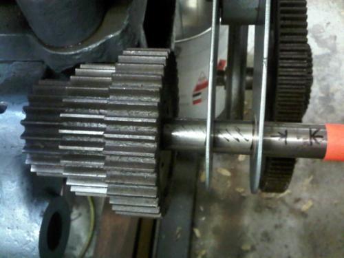
The next picture shows the alignment clearly. The 1" shaft in there now will be machined to take the driven chain sprocket out on the right hand end. The arrows indicate the alignment with the drive sprocket. I will build a spacer that will sit between the two brackets I fabricated and also between the gear cluster and the left hand bracket. There is a long way to go to get the feed running.

Hunting American dentists since 2015.
Posts: 4
Threads: 1
Joined: Sep 2013
Location: Australia
Will do a photo shoot for you and just ask what detail you want will detail the worm too. it can be used as a taper turn too . when i go to visit am sure there is another similar lathe with the worm drive set up on power feed shaft. he makes his own drilling rods for his water boring operation cuts a 4 tpi tapered thread on about 2 inch pipe from memory. Fine day today and will fire up the camera.
My old girl here now tizzied up with a splash of dulux by former owner. came from a garage in avoca central Vict and was taken out of service under work cover orders. they had it there for years put on an apprentice and work cover visited the garage and condemned it due to flat belt drive.by the look it is in good condition and it measures up ok some teeth off here and there including the worm drive[helical gear] the owner took it home and cleaned it up and painted and unfortunately passed on, Bought from family but sadly missed this by 2 weeks was a hercus lathe bought brand new in a box ex army .they were fitted on ser 2 landrovers for field work shop used fitted accross back of tray at rear.
Did notice the chain drive mod on your lathe but this has all original gear drive and all change gears up to 120 teeth Cheers John.
JOHN.ASHBURN, proud to be a member of MetalworkingFun Forum since Sep 2013.
Posts: 4,683
Threads: 93
Joined: Feb 2012
Location: Perth, Australia
Thanks John. I'd appreciate any pictures of the feed drive that you are able to get.
Hunting American dentists since 2015.
Posts: 4,683
Threads: 93
Joined: Feb 2012
Location: Perth, Australia
Some of you may have seen my latest post in my steady rest thread. If so, you would have seen that I used the T-slots on the carriage to hold a fixture in place to allow me to drill the holes in the frame.
When I got this lathe, the T-slots had rusted chips in there and unfortunately, most of them are still in there, as a solid, rusty reminder to keep one's lathe clean! As they were not easy to remove and I didn't want to waste time and risk potential damage to a feature that I never thought I would use, I never gave them much thought. Well fast forward a few years and I can now see the benefit of having T-slots. I'll have to take some pictures when I'm next in the workshop, as I have none that show the problem.
So - my question is: how do I remove them?
Hunting American dentists since 2015.
Posts: 3,795
Threads: 183
Joined: Jun 2012
Location: Farmington Hills, Michigan
If they are on a flat surface, can't you just machine them off?
Maybe pictures are required.
Tom
Posts: 4,369
Threads: 178
Joined: Feb 2012
Location: Missouri, USA
I would start by soaking them in Kroil (penetrating oil) for a few days to try and loosen up the bond between them.
Then perhaps place a block of wood on top of the t-slots and go over it with an air hammer? Maybe it would shake them loose from the slots. 
Just thinking out loud... 
Willie
Posts: 4,683
Threads: 93
Joined: Feb 2012
Location: Perth, Australia
(10-13-2013, 09:56 AM)TomG Wrote: If they are on a flat surface, can't you just machine them off?
Maybe pictures are required.
Tom
As per my previous post:
(10-13-2013, 12:40 AM)Mayhem Wrote: ...I'll have to take some pictures when I'm next in the workshop, as I have none that show the problem...

These are chips that have fallen into the T-slots and rusted into place, so to mill them out I would essentially have to ensure that the slots are perfectly lined up on my mill (which is in bits). Given the undulating surface that is the bottom of the carriage, lining things up would take an awful amount of work.
Willie, I'll give that a try. Perhaps a 50/50 mix of acetone and ATF would be a good starting point. I have considered getting in there with the air hammer and seeing if I can dislodge the material that is in the firing line.
I'm not even going to see the workshop for another week or so...
Hunting American dentists since 2015.
|


 I'm sure Chinglish is infectious.
![[Image: TomsTechLogo-Profile.png]](http://tomstechniques.com/wp-content/uploads/2013/11/TomsTechLogo-Profile.png)


